





Description
Key Technical Specifications
| Parameter | Specification / Value |
| Processor Architecture | Intel Core 2 Duo (Merom) up to 2.16 GHz |
| System Cache | Up to 4 MB L2 Cache |
| System Chipset | Intel 945GME Express / ICH7-M Peripheral Controller |
| System Memory | 2 GB DDR2 SDRAM (667 MHz system and memory bus) |
| Form Factor | 6U (4HP) Single-Slot Eurocard (VMEbus Standard) |
| Mass Storage Support | Up to 8 GB bootable CompactFlash via secondary IDE port |
| Front Panel Interfaces | 2 × Gigabit Ethernet (RJ45 via Intel 82571), 1 × RS232 (DB9), 2 × USB 2.0, 1 × PS/2 KB/Mouse, 1 × SVGA Video |
| Rear I/O via P2 | 2 × USB 2.0, 2 × SATA interfaces, 1 × COM2 Serial Port |
| Expansion Slot | One PCI-X capable PMC (PCI Mezzanine Card) site with EasyRail mounting |
| Non-Volatile Memory | 32 KB of non-volatile SRAM (NVRAM) for critical variable retention |
| Power Consumption | +5 VDC (±5%), ~3.5 A typical / 4.8 A maximum |
| Cooling Requirement | Forced air cooling, 400 LFM minimum at the heatsink outlet |
| Operating Temperature | 0°C to +55°C (32°F to 131°F) under specified airflow limits |
| Dimensions | 233.4 mm H × 160.0 mm D × 20.3 mm T (9.2 × 6.3 × 0.8 inches) |
Product Introduction
The GE Fanuc / Abaco Systems V7768-312000 is an industrial-grade 6U VME Single Board Computer optimized for embedded automation, process simulation, and defense infrastructure. Powered by the Intel Core 2 Duo architecture and the 945GME Express chipset, this board delivers the high-speed data execution and multi-threaded calculations necessary for complex real-time operations.
This specific configuration features 2 GB of high-speed DDR2 system memory and an integrated PCI-X PMC expansion slot equipped with the EasyRail mounting mechanism. Front-panel connectivity provides dual Gigabit Ethernet links, high-resolution SVGA video, and multiple USB 2.0 ports. These features allow operators to deploy local processing nodes, high-speed telemetry links, and localized human-machine interfaces without straining the VME backplane’s native bandwidth.
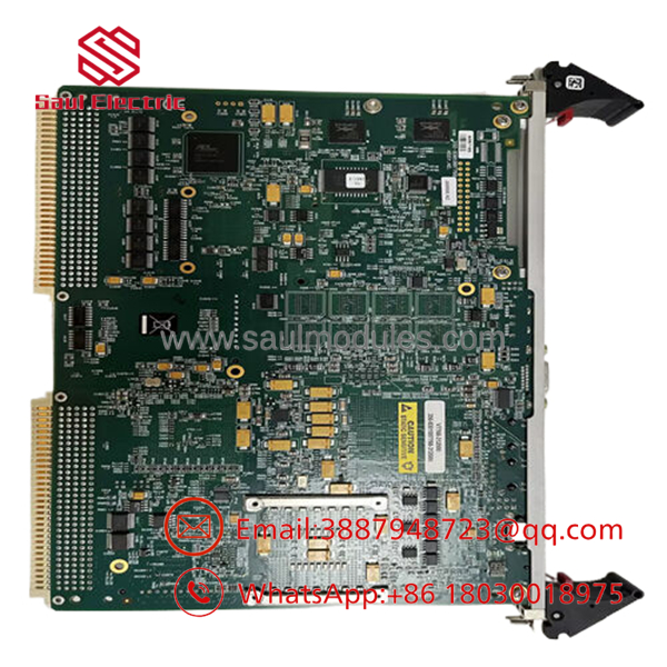
- V7768-312000
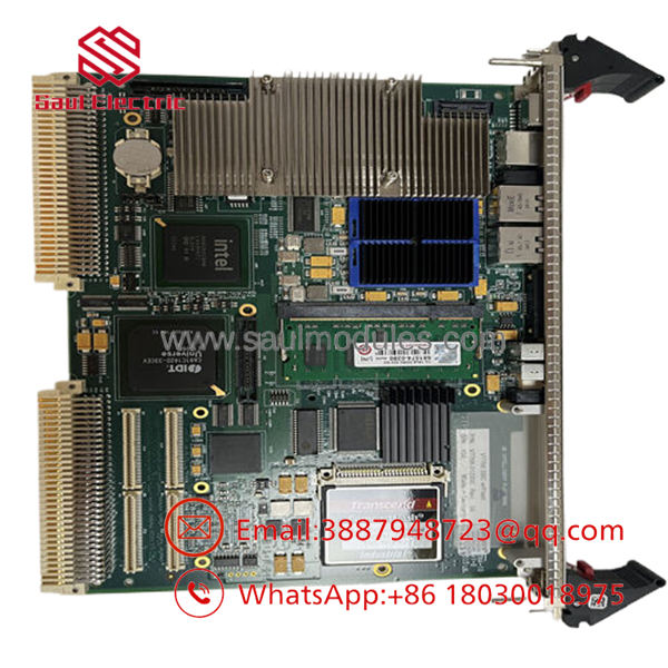
- V7768-312000
【Core Strategy 1: SOP Quality Transparency】
Because real-time embedded systems handle highly critical compute networks, all V7768-312000 cards undergo strict physical and functional verification before being certified for shipment.
1. Inbound Inspection & Traceability
- Verification & Mapping: Internal serial allocations and printed hardware revision marks are compared against OEM build logs from GE Fanuc / Abaco database archives.
- Microscopic Visual Screening: The logic board is scanned under magnification to identify micro-fractures in solder balls, BGA array lifting, dust inside the SODIMM slot, or heat scoring on the processor voltage regulators.
- Pin and Connector Evaluation: Gold-plated VME P1 and P2 pin arrays are checked for straightness, alignment, and contact wear.
2. Live Functional Testing
- Enclosure Testing: The V7768-312000 board is populated with a standard test SODIMM and slotted into an operational 6U VMEbus test chassis connected to an independent auxiliary power station.
- BIOS Diagnostic Sweep: The card runs through its full power-on self-test routines to confirm clear memory indexing, PCI bus allocation, and video terminal stabilization.
- Operating System Benchmarking: Technicians boot the board into an active VxWorks or Linux test kernel, running real-time processing tasks for 12 hours while monitoring thread performance and thermal characteristics.
- I/O Port Diagnostics: Loopback tests verify data flow across both front RJ45 Gigabit Ethernet channels, front/rear USB links, and the serial COM interface.
3. Electrical Parameter Testing
- Voltage Integrity Audits: Multimeters track active +5 VDC and +12 VDC rails at the board level to confirm current consumption stays within specified tolerances.
- Ground Isolation Checks: Ground traces are verified to prevent unexpected electrical noise paths across the VME backplane framework.
4. Firmware & Configuration Verification
- BIOS Standard Setup: The system flash BIOS is documented and set to standardized defaults or configured to align with specific customer build criteria.
- DIP Jumper Auditing: The physical configuration jumpers governing boot device priority, clock multipliers, and VME controller settings are audited and restored to factory specifications.
5. Final QC & Packaging
- ESD Shielding Protection: Cleared boards are handled using grounded static wrist links and sealed inside multi-layer ESD anti-static packaging.
- Secure Box Enclosure: The packaged board is placed inside custom foam padding within a double-walled corrugated outer box to prevent damage from transport shocks. The box is sealed with a dated QC validation label.
Installation & Configuration Guide
Stage 1: Pre-Installation Preparation
- Estimated Time: 15 minutes
- ⚠️ Safety First: Power down the master VME enclosure entirely. Turn off all primary power switches supplying the rack backplane. Tag out the main power feeds. Wait 3 minutes to ensure the enclosure power supplies discharge completely.
- Tools Required: ESD wrist grounding strap, anti-static work pad, fine slotted screwdriver, and a Phillips screwdriver for PMC module retention.
- Configuration Backup: If the old SBC remains responsive, connect a serial terminal to COM1, enter the BIOS configuration menus, and record all specific custom drive mappings, interrupt requests (IRQs), and VME base address settings.
Stage 2: Removing the Old Module
- Estimated Time: 10 minutes
- Steps:
- Clip your ESD wrist strap to an unpainted, grounded structural bar on the system rack frame.
- Disconnect all front-panel cabling, including Ethernet RJ45 patch cables, USB links, and SVGA display monitors.
- Release the upper and lower injector/ejector handles on the V7768 card face by pressing their locking tabs and pivoting the handles outward.
- Slide the board slowly out along the sub-rack card guides, keeping the card horizontal to avoid contacting adjacent processing modules.
- Place the pulled module directly onto an anti-static surface sheet.
Stage 3: Installing the New Module
- Estimated Time: 15 minutes
- Steps:
- Inspect the new V7768-312000 unit to confirm the layout matches the old hardware revision.
- If an optional PMC daughterboard is required, mount it to the onboard PCI-X slot using the EasyRail mounting screws before sliding the SBC into the main rack.
- Check the internal configuration jumpers against your baseline record to ensure proper boot device priorities and VME address allocations are set.
- Align the board edges with the target slot tracks inside the 6U rack. Slide the module inward until the injector/ejector handles touch the chassis lip.
- Push both handles inward simultaneously to seat the P1/P2 connector pins firmly into the backplane socket, then tighten the captive faceplate retention screws.
- Self-Checklist:
- [ ] Injector handles fully locked and flush against the front plate.
- [ ] Mechanical alignment of all front-panel interface ports.
- [ ] PMC expansion board screws secured tightly.
Stage 4: Power-On & Testing
- Estimated Time: 20 minutes
- Power-On Steps:
- Clear all loose tools from the rack area and re-apply power to the main VME enclosure.
- Watch the front plate status lights. The boot diagnostic phase should clear within seconds, and a steady display output should appear on your connected monitor terminal.
- Press
DELorF2during the initial boot screen to access the BIOS setup utility. Confirm the system recognizes the full 2 GB DDR2 RAM array and the bootable CompactFlash card. - Load the target operating system (VxWorks, Linux, or Windows XP Embedded).
- Monitor the system logs to ensure no VMEbus collision warnings or network driver timeout messages are generated.
- ⚠️ Troubleshooting Note: If the board does not boot and the rack fans cycle erratically, check that the card is fully seated in the backplane slot. Worn or misaligned P1/P2 connectors can cause poor electrical contact on the primary +5 VDC power pins.
【Core Strategy 2: Technical Pitfall & Survival Guide】
1. Airflow and Thermal Management Failures
The Intel Core 2 Duo processor on the generates significant heat compared to older low-power RISC processors. ❗ Operating this module without sufficient forced-air cooling will lead to thermal throttling or sudden safety shutdowns. The board requires a minimum of 400 LFM (Linear Feet per Minute) of continuous airflow across its onboard heatsink. If your rack’s fan trays are old or dirty, the CPU temperature can exceed its +55°C operational limit under heavy load, leading to intermittent calculation errors. Always inspect and clean your fan assemblies before deploying this card.
2. PMC Expansion Card Screw Stripping
The EasyRail mounting configuration makes attaching PMC mezzanine cards straightforward, but using wrong-sized tools or over-tightening the retention screws can strip the threads on the standoffs. ❗ A loose PMC card can cause intermittent PCI bus errors and system lockups. Use a properly sized precision screwdriver, and apply minimal torque when locking down expansion cards to prevent thread damage.
3. VMEbus Base Address Conflicts
When setting up a replacement card within an active multi-processor sub-rack layout, you must carefully verify the jumper settings that govern VME slot identification and system controller status. If the new card is jumpered as the primary System Controller while another card in the same rack already performs that function, the resulting bus arbitration conflict will freeze data traffic across the entire VME backplane. Always match the hardware jumper settings of your replacement board to the layout of the old module.
4. CompactFlash Card Compatibility Issues
The onboard CompactFlash socket is highly useful for local operating system storage, but the integrated IDE controller is sensitive to the formatting and speed ratings of older CF media. Using consumer-grade or incompatible flash cards can lead to persistent boot disk errors or data corruption under heavy read/write cycles. Always use high-quality, industrial-grade CompactFlash media that supports Fixed Disk Mode to ensure consistent boot reliability.
5. Backplane Contact Wear and Pin Damage
The 6U VME form factor uses high-density multi-pin arrays to route system data. If a module is inserted at an angle or forced into a slot with worn guide rails, these pins can bend or break. ❗ Never force the module into the slot. If the card does not slide completely flush with the external framework under gentle pressure, pull it out and inspect the pins using a flashlight. Repairing a damaged backplane requires completely dismantling the relay chassis.
Frequently Asked Questions (FAQ)
Can I hot-swap the -312000 processor board while the VME rack is running?
No. The standard VMEbus architecture does not inherently support hot-swapping for primary single board computers. Extracting the processor card while the backplane is energized will disrupt bus timing signals, generate severe electrical noise on the data lines, and potentially cause data corruption or physical component damage across other modules in the rack. Always turn off the enclosure power supply before extracting the board.
What is the difference between the Core 2 Duo and Celeron M hardware versions of the ?
The Core 2 Duo version (fon this configuration) features dual-core processing up to 2.16 GHz and a 4 MB L2 cache, making it ideal for high-throughput computing tasks. The Celeron M variant runs at a lower 1.07 GHz clock rate with a smaller 1 MB cache. However, because it generates less heat, the Celeron M version offers an extended operating temperature limit up to +70°C, compared to the +55°C limit for the Core 2 Duo card.
Does this board support modern 64-bit operating systems?
The Intel Core 2 Duo processor features a 64-bit instruction set architecture, ang the to run compatible 64-bit versions of Linux or specialized real-time operating systems. However, the system chipset and onboard controllers are optimized around standard 32-bit legacy deployments like Windows XP Embedded and specific older branches of VxWorks. Verify driver availability before planning a migration to a modern 64-bit OS environment.
Why is the system BIOS not saving configuration changes after power cycles?
This issue typically indicates that the onboard 32 KB non-volatile SRAM backup cell has failed or discharged over its extended storage lifespan. When this happens, the board resets to its default factory parameters whenever control power is removed. To fix this issue, you will need to replace the onboard NVRAM backup component or send the module to an authorized repair facility for servicing.
Can I connect a modern SATA SSD directly to the single board computer?
The provides two SATA interfaces, but these lines are routed directly through the rear P2 connector to maintain a single-slot footprint. To connect external SATA drives, you will need a compatible Rear Transition Module (such as the ACC-0602RC-100 or ACC-0603RC-100). This breaks out the SATA, USB, and secondary serial connections to standard headers on the back panel of the enclosure.




 Start Chat


