





Description
Key Technical Specifications
| Parameter | Value / Specification |
|---|---|
| System Architecture | GE Entellisys Low Voltage Switchgear Framework |
| Model / Catalog Code | WES5162-9101 |
| Primary System Role | Localized Breaker Interface / Communication Node Hub |
| Network Redundancy | Dual-channel deterministic Entellisys Control Bus links |
| Isolation Barrier | Optically isolated I/O tracks to safeguard logic from field transients |
| Data Synchronization | Sub-millisecond continuous point scanning and parameter tracking |
| Mounting Footprint | Specialized internal switchgear chassis or DIN-rail track configurations |
| Chassis Shielding | Rugged, fully enclosed steel housing providing superior EMI/RFI protection |
| Control Logic Hookup | Removable heavy-duty terminal block strips with locking mechanisms |
| Operating Temperature | −20 to +65°C (−4 to +149°F) stable working environment |
Product Introduction
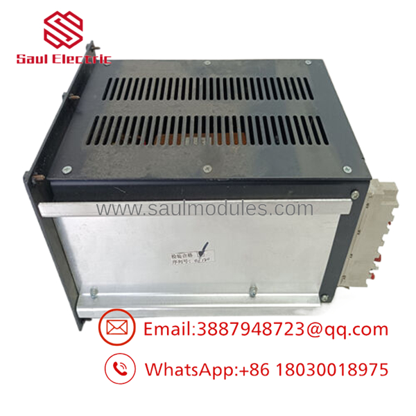
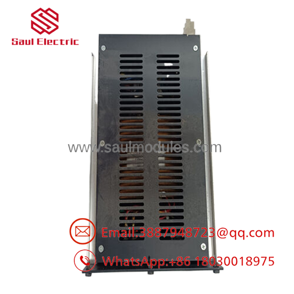
The GE WES5162-9101 is a high-reliability Remote Messenger and System Control Bus Interface Module developed specifically for the GE Entellisys™ Low Voltage Switchgear ecosystem. Positioned between the centralized switchgear processing computers (such as the WES5120 CPU) and individual motor control or breaker positions, the WES5162-9101 aggregates local diagnostic signals, tracks contact positions, and routes deterministic trip and close commands across the system.
Encased in a robust, heavy-duty steel enclosure, the module is engineered to handle the harsh, high-electromagnetic-interference (EMI) environments typical of main electrical rooms and substations. It interfaces directly with the dual redundant Entellisys Control Bus, ensuring that critical safety data—such as zone selective interlocking (ZSI) statuses or breaker tracking coordinates—retains a redundant communication path. This distributed design minimizes local wiring inside the gear while maintaining sub-millisecond coordination for fault containment.
- WES5162-9101
- WES5162-9101
Installation & Configuration Guide
Stage 1: Pre-Installation Preparation (Estimated Time: 15 minutes)
- ⚠️ Safety First: The WES5162-9101 module interfaces directly with control structures capable of opening and closing low-voltage power breakers. Never extract or insert this interface module while the switchgear’s auxiliary control power bus is energized. Unintended command bridging can occur, causing accidental power outages or machinery activation. Execute a complete lock out/tag out (LOTO) on the 24 VDC auxiliary control rails supplying this bucket.
- Tools Required: Grounded anti-static wrist strap, small flathead terminal screwdriver, cross-head screwdriver, and a laptop running Entellisys System Configuration software.
- Data Backup: Connect your laptop to the system network interface before turning off power. Back up and archive the existing node address maps, physical terminal assignment matrices, and the complete layout map for the local switchgear section.
Stage 2: Removing the Old Module (Estimated Time: 10 minutes)
- Affix your anti-static grounding wrist strap to a verified bare-metal structure inside the auxiliary control enclosure.
- Label each network cable and communication link attached to the module’s interface ports to ensure they are reconnected correctly. Disconnect the lines carefully.
- Unplug the removable terminal block connectors routing low-voltage signal wiring into the unit’s base.
- Remove the mounting bolts securing the metallic module enclosure to the backplate frame, or release the heavy-duty rail clips.
- Slide the module cleanly out of its slot and place it inside an ESD protective shield wrap.
Stage 3: Installing the New Module (Estimated Time: 10 minutes)
- Unpack the new module, ensuring no debris or static discharge impacts the rear connection surfaces.
- Position the module casing over the original enclosure mounting points or lock it firmly onto the internal DIN-rail track.
- Drive home the structural mounting screws or engage the integrated locking clips to ensure a solid mechanical and grounding bond with the backplate.
- Reinsert the labeled low-voltage terminal strip plugs, pushing firmly until their retention clips click into place.
- Connect the redundant control network communication patches back to their matching port designations.
Stage 4: Power-On & Node Configuration (Estimated Time: 20 minutes)
- Re-engage the 24 VDC auxiliary control power feed breaker to energize the local switchgear section.
- Monitor the diagnostic indicators on the faceplate of the during initialization:
- The primary status lights should stabilize into a steady green pattern.
- Network indicators should initiate a high-frequency flashing cycle as communication is re-established.
- ⚠️ Troubleshooting: If a red Fault or communication error indicator remains illuminated, connect through your configuration utility to check for a node ID collision or an uninitialized network address.
- Launch your Entellisys configuration tool, run an auto-discovery scan to log the new module’s physical barcode signature, and download the archived operational configuration parameters to restore full system synchronization.
Frequently Asked Questions (FAQ)
Can the module be hot-swapped while the switchgear control bus is powered?
No, hot-swapping this module is not supported. The acts as an active link between localized breaker signals and the main control bus. Removing or inserting this module while power is applied can introduce voltage transients on the shared data highway, which can corrupt signal frames, cause network communication timeouts, or trigger accidental breaker operations.
What is the specific purpose of the “Remote Messenger” role in Entellisys setups?
In the Entellisys platform, the “Remote Messenger” modules function as specialized distributed I/O concentrators. Rather than routing hundreds of individual copper field wires from every auxiliary breaker contact back to a central processor, a single module handles all localized contact scanning within its designated section. It then compresses this data and transmits it digitally across a high-speed redundant network bus.
How do I clear a “Node ID Mismatch” error after installing a replacement board?
This error occurs because the main system processor is looking for the unique electronic serial tag or node address assigned to the old module. To clear it, connect your engineering laptop to the network via the Entellisys engineering toolset, go to the hardware configuration layout, select the replacement node position, use the “Discover/Assign New ID” command to log the new card’s identity, and download the updated configuration file.
Why is the module encased in a heavy-duty metal housing instead of plastic?
Low-voltage switchgear lineups handle thousands of amperes of electrical current, which creates intense electromagnetic fields, voltage spikes, and localized radio frequency noise. A plastic housing would allow this interference to corrupt the high-speed data moving through the module. The heavy-duty steel enclosure acts as a Faraday shield, isolating the internal microelectronics from ambient noise to ensure dependable operation.
Why are these parts sold as “New Surplus” rather than direct from current factory lines?
As industrial power management architectures advance through newer generation rollouts, legacy hardware variations like the original Entellisys components are phased out of high-volume serial assembly lines by the OEM. Our inventory consists of New Original / New Surplus units—unused factory components sourced directly from plant modernization surpluses, canceled infrastructure reserves, or warehouse buybacks. This gives you direct access to authentic replacement parts without long production lead times.



 Start Chat


