





Description
Product Introduction & Engineering Value
The engineering value of the Honeywell 05701-A-0361 centers on its specialized raw sensor interface. Unlike 4-20mA loop cards that require an active transmitter at the detector head, this module contains the exact balance circuitry required to drive a remote, unamplified catalytic bead sensor. By shifting the configuration and calibration controls directly into the control room rack, it eliminates the need to perform tricky field calibrations in hazardous areas.
Operating in explosive gas monitoring environments requires absolute loop security, which this hardware delivers through single-channel isolation. If an operational component fails or a field wire shorts out on this loop, the remaining cards in the System 57 rack stay completely active. It remains a vital component for facilities that depend on standard catalytic bead sensing grids to monitor for combustible gas risks.
Technical Specifications
| Parameter | Specification Detail |
| Input Sensor Type | 3-wire catalytic bead bridge sensor head |
| Drive Current Range | Adjustable constant current source up to 500mA |
| Measurement Range | 0 to 100% LEL (Lower Explosive Limit) |
| Interface Elements | Multi-segment LCD concentration screen with dedicated status LEDs |
| Alarm Outputs | 3 x SPCO configuration relays (rated up to 5A at 250V AC) |
| Fault Output Status | Dedicated NC/NO fault monitoring contact ring |
| Operational Supply | 24V DC nominal input voltage |
| Maximum Dissipation | Up to 5.5 Watts (dependent on catalytic bead drive current configuration) |
Field Application & The “Trench” Experience
A refining facility was hit with an unexpected instrument breakdown during a scheduled startup loop review: a catalytic LEL sensor monitoring a critical hydrogen compressor seal room went completely dark at the rack. The original control unit had experienced a shorted drive circuit, dropping the sensor current to zero. The compressor area could not be safely cleared for startup without functional LEL visual indications.
Our warehouse shipped a New Surplus 05701-A-0361 card straight out to the plant floor. The instrumentation team unlatched the failed card, verified that the onboard sensor drive current jumper matched the 200mA specification for the field head, and seated the module into the empty slot. Running a target zero and span calibration gas check at the sensor head synced the bridge loop immediately, allowing the facility to bring the compressor skids online on schedule.
Niche Application Scenarios:
- Offshore Drilling Mud Pit Enclosures: Monitors direct LEL gas build-ups under severe temperature fluctuations where localized transmitters degrade.
- Turbine Enclosure Fuel Line Monitoring: Triggers automated ventilation sweeps and fuel line shut-offs via low-latency, card-level relays.
- Solvent Storage Vault Scanners: Evaluates ambient concentrations of evaporated hydrocarbons without needing explosive-proof transmitters in the vault.
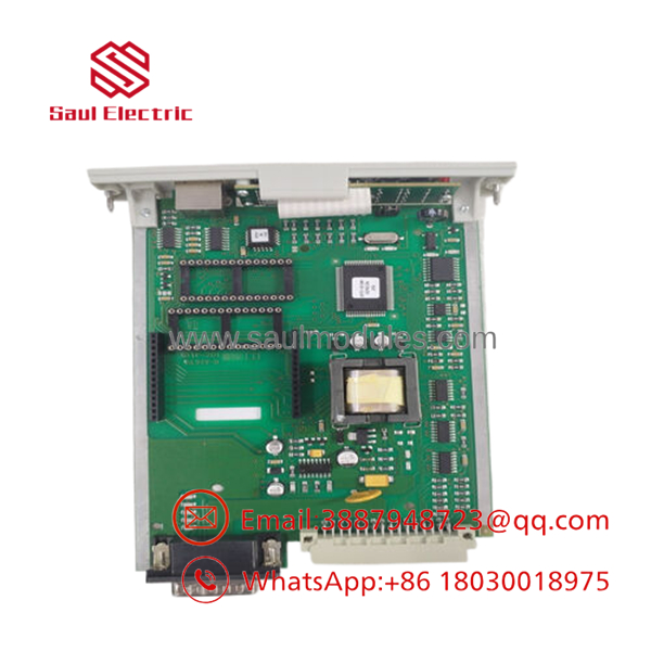
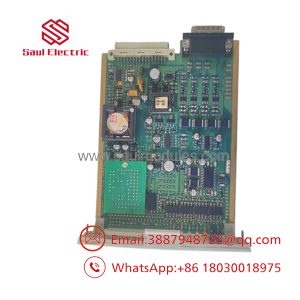
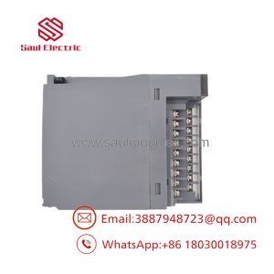
- 05701-A-0361
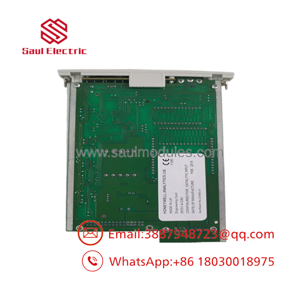
- 05701-A-0361
Transparency SOP: QA & Testing
Every 05701-A-0361 card passing through our evaluation workshop undergoes a rigorous safety check sequence:
- Bridge Balancing Sweep: We connect the input pins to a simulated variable resistance bridge, validating that the internal scaling circuits track from 0% to 100% LEL with zero drift.
- Constant Current Regulation Test: The sensor drive circuit is loaded at various resistance settings to ensure the module maintains a rock-solid, precise mA output to power the remote beads.
- Relay Contact Verification: All three alarm outputs and the system fault circuit are run through rapid open/close test sequences under load to verify low contact resistance.
- Rack Extraction Integrity Check: The physical multi-pin backplane connector is checked for alignment and structural stability to ensure clean installation.
The Veteran’s Tech Trap Guide
⚠️ CRITICAL RETROFIT WARNINGS
- The Sensor Current Burnout Trap: This card acts as a constant current power supply for the remote catalytic sensor beads. Before you slide a new card into the rack, you must confirm that the onboard sensor drive current jumpers match your specific sensor head specification (e.g., 200mA, 335mA, or 500mA). Leaving the card set to a high current output when connecting a low-current sensor will instantly melt the fine platinum wire inside the remote catalytic bead, destroying the field instrument.
- 4-20mA Incompatibility: Do not attempt to wire a standard 2-wire or 3-wire 4-20mA transmitter into this card. The 05701-A-0361 is specifically engineered for direct raw bridge connections; utilizing it with a current loop device requires a different model, such as the 05701-A-0302.
- Line Resistance Balance: Because the raw sensor bridge voltage is relatively low, long cable runs between the rack and the sensor will introduce line resistance that affects calibration. Always perform a complete zero and span check at the terminal box after swapping a card to tune out the copper wire resistance.
Dynamic FAQ
- Q: Can this card be used to monitor toxic gases like Hydrogen Sulfide in parts-per-million (PPM)?
- A: No. Toxic gas sensors generally require electrochemical or 4-20mA loops. The 05701-A-0361 is explicitly designed for high-temperature catalytic bead configurations calibrated to measure explosive concentrations in the LEL range.
- Q: How do I adjust the alarm setpoints on this specific module?
- A: Setpoints are adjusted directly through the front panel engineering interface using a specialized magnetic wand or calibration tool, allowing you to cycle through menus and alter A1, A2, and A3 trip parameters without pulling the card out of the rack.
- Q: Does your New Surplus inventory for this item include a fresh front panel bezel plate?
- A: Yes, all of our New Surplus units arrive complete as integrated single-channel modules, including the full front vertical bezel layout with its pre-fitted LCD screen, status indicator lights, and securing screws.
- Q: What happens if one of the remote sensor wires breaks during operation?
- A: The card’s internal diagnostics will immediately detect an open-circuit bridge state. The module will light the bright amber front panel “Fault” LED, open the dedicated fault relay loop, and drive the display to a clear fault code state to prevent false safety clears.

 Start Chat


