





Description
Core Product Summary (Brand / Model / Key Attributes)
The Honeywell FTA-T-14 is a 16-channel fail-safe analog input Field Termination Assembly (FTA) engineered for integration with Honeywell Fail-Safe Control (FSC) safety systems. Functioning as the physical bridge between field instrumentation and system logic modules, it provides signal routing, overcurrent protection, and field wiring termination for critical process safety and emergency shutdown applications.
Designed to accommodate 0(4)–20 mA analog input signals, the FTA-T-14 organizes wiring across screw terminals and routes connections to logic modules using standard System Interconnection Cables (SICs). The module features individual group fuses (250 mA slow-acting), supporting a maximum voltage capacity of up to 36 V AC / 50 V DC (Overvoltage Category III) or 125 V AC / 150 V DC (Overvoltage Category II). Designed for DIN rail mounting (TS32 / TS35), it handles field conductor sizes up to 2.5 mm² (AWG 14) and maintains channel-to-logic galvanic isolation up to 1500 V AC.
Key Technical Specifications
| Parameter | Specification |
| Product Type | Fail-Safe Analog Input Field Termination Assembly (FTA) |
| System Compatibility | Honeywell Fail-Safe Control (FSC) System |
| Channel Capacity | 16 Channels (2 groups of 8 channels) |
| Input Signal Compatibility | 0–25 mA DC (compatible with standard 0/4–20 mA transmitters) |
| Input Resistance | 250 Ω (±1%) |
| Maximum Voltage Limits | 36 V AC / 50 V DC (Category III); 125 V AC / 150 V DC (Category II) |
| Isolation Rating | 1500 V AC for 1 minute (Channel-to-Logic / Channel-to-Channel) |
| Protection Fuse | 250 mA slow-acting (5 × 20 mm or 5 × 25 mm format) |
| Field Wiring Connections | Screw terminals (16 groups of 4 terminals; 2 groups of 2 for power; 2 earth terminals) |
| System Connection | System Interconnection Cable (SIC) connector (1FF × 16 format) |
| Maximum Conductor Size | 2.5 mm² (AWG 14); Strip length: 7 mm; Tightening torque: 0.5 Nm |
| Dimensions (L × W × H) | 145 mm × 70 mm × 65 mm |
| Mounting Standard | TS32 / TS35 × 7.5 DIN Rail |
| Certifications & Approvals | CE, UL compliant; Class I, Division 2 compliant; SIL 3 capable |
Detailed Product Overview
The Honeywell FTA-T-14 serves as a termination interface within industrial safety instrumented systems (SIS) and high-availability process automation architectures. As part of the Honeywell Fail-Safe Control (FSC) hardware lineup, the assembly interfaces field-mounted transmitters—such as pressure, temperature, flow, and level sensors operating on 0–20 mA or 4–20 mA current loops—directly to system input processing hardware.
Field signals enter the FTA-T-14 through screw terminal blocks and pass through onboard current-limiting components and protective fuses before traveling across System Interconnection Cables (SICs) to the central processing system. The 16 input channels are organized into two distinct groups of eight, each sharing a 0 V common line. This structured arrangement streamlines power distribution and isolation management across loop-powered or externally powered transmitter configurations.
By handling signal landing, current loop impedance matching via internal 250 Ω precision resistors, and fault protection at the termination boundary, the assembly protects high-density logic circuits from field-side electrical disturbances. The physical design allows installation directly inside marshalling cabinets or termination panels, facilitating organized wiring runs and straightforward multi-channel diagnostics.
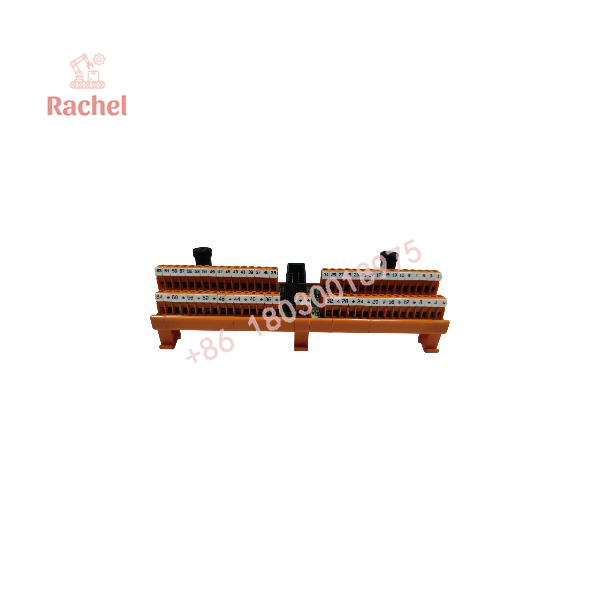
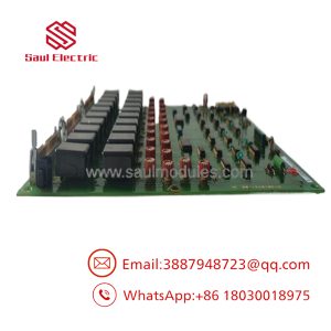
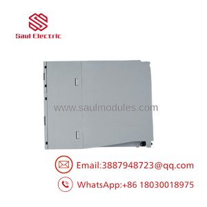
FTA-T-14
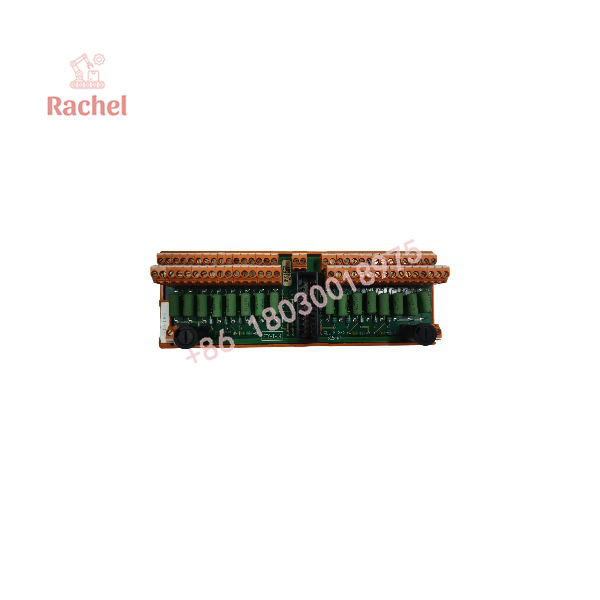
FTA-T-14
Engineering Selection Highlights
- 16-Channel Fail-Safe Architecture: Supports high-density analog sensor landing while maintaining safety-instrumented system integrity up to SIL 3 application levels.
- Integrated Precision Resistors: Includes internal 250 Ω (±1%) input resistors to convert 0/4–20 mA field current signals directly into required voltage levels for system processing.
- Overcurrent & Fault Protection: Incorporates 250 mA slow-acting fuses across channel groups to isolate loop faults and protect internal system logic.
- 1500 V AC Galvanic Isolation: Meets standard safety isolation thresholds between field loops and system processing electronics per IEC 61010-1.
- Standardized Cable Interfacing: Utilizes 1FF × 16 SIC connectors to enable clean, direct cabling to FSC rack modules without manual point-to-point internal wiring.
- Standard Industrial Mounting: Designed for standard TS32 and TS35 DIN rails, simplifying integration into standard marshalling enclosures.
System Compatibility & Integration Requirements
| Item / Dependency | Verified Compatibility or Requirement | Practical Note |
| Base Safety System | Honeywell Fail-Safe Control (FSC) | Designed for direct operation with FSC analog input processing modules. |
| System Interconnection | System Interconnection Cable (SIC) | Requires 1FF × 16 cable assembly for link to system rack. |
| Field Wiring Terminals | Screw terminal blocks (Max 2.5 mm² / AWG 14) | Torque terminals to 0.5 Nm (0.37 ft-lb) during installation. |
| External Power Support | Auxiliary 24 V / 30 V DC supply connections | Terminal blocks include dedicated power pass-through and earth ground points. |
| Mounting Hardware | DIN Rail (TS32 or TS35 × 7.5) | Requires a minimum DIN rail length of 146 mm for proper board mounting. |
Dimensions, Mounting & Connection Notes
The Honeywell FTA-T-14 measures 145 mm in length, 70 mm in width, and 65 mm in total height. It installs onto standard TS32 or TS35 × 7.5 DIN rails, requiring at least 146 mm of continuous rail space for clear placement.
Field connections use screw terminals capable of accepting solid or stranded copper conductors up to 2.5 mm² (AWG 14). Terminal screws require a stripping length of 7 mm and a tightening torque of 0.5 Nm (0.37 ft-lb) to maintain secure contact. Grounding is provided via dedicated earth screw terminals (T64/T), which must be connected to the cabinet ground bar to ensure proper shielding and surge suppression performance.
FAQ
What is the Honeywell FTA-T-14?
The Honeywell FTA-T-14 is a 16-channel fail-safe Field Termination Assembly designed to interface 0(4)–20 mA analog input sensors with Honeywell Fail-Safe Control (FSC) systems.
How many channels does the FTA-T-14 support?
It supports 16 analog input channels, arranged in two groups of eight channels.
What input signal types are compatible with the FTA-T-14?
The assembly handles 0–25 mA DC range signals, making it fully compatible with standard 0–20 mA and 4–20 mA field transmitters.
What type of fusing does the assembly use?
It uses 250 mA slow-acting fuses (5 × 20 mm or 5 × 25 mm format) for fault protection.
How is the FTA-T-14 connected to the main control system?
The unit connects to the system rack via a System Interconnection Cable (SIC) using a 1FF × 16 connector interface.
What conductor size can be used on the field terminal blocks?
The terminal blocks accept wire sizes up to 2.5 mm² (AWG 14).
What DIN rail standards are supported for mounting?
The board mounts on standard TS32 or TS35 × 7.5 DIN rails.
Verification & Troubleshooting Notes
When diagnosing field signal or connection issues on the FTA-T-14:
- Power & Loop Voltage Checks: Measure voltage across external power terminal pairs to confirm the presence of required loop power (typically 24 V DC to 30 V DC).
- Fuse Integrity Verification: If an entire group of eight channels loses signal, check the continuity of the 250 mA slow-acting fuse dedicated to that group.
- Loop Resistance Verification: Verify that field loop resistance accounts for the internal 250 Ω precision resistor on the FTA assembly.
- Wiring & Terminal Inspection: Inspect screw terminal connections for proper wire strip length (7 mm) and verify torque settings (0.5 Nm) to prevent high-resistance joints or open loops.
- Grounding Checks: Ensure dedicated earth ground terminals (T64/T) are bonded to cabinet earth ground to prevent noise interference on sensitive analog current signals.

 Start Chat


