





Description
Product Introduction & Engineering Value
The KUKA KSD1-16 is a robot-axis servo amplifier used inside KUKA KRC2 controller cabinets. It takes energy from the controller’s DC intermediate circuit and regulates the three-phase motor current required by an individual robot axis.
The important number in KSD1-16 is the drive’s 16 A maximum acceleration-current class, rather than a conventional 16 kW motor rating. KUKA documentation identifies the KSD1-08/16/32 family by maximum acceleration current, with the KSD1-16 providing an 8 A rated current and 16 A maximum acceleration current.
This distinction matters when replacing a failed module. The KSD1-16 must be matched to the robot axis, motor, controller configuration, and KUKA article number. It should not be selected simply because its current rating appears higher than another KSD module.
Technical Specifications
| Parameter | KSD1-16 |
|---|---|
| Manufacturer | KUKA |
| Model | KSD1-16 |
| KRC Platform | KRC2 |
| Drive Type | Servo drive module |
| Rated Current | 8 A |
| Maximum / Acceleration Current | 16 A |
| Intermediate Circuit | 0–740 VDC in KUKA technical documentation |
| Other Published Version Data | 0–770 VDC |
| Motor Output | 3-phase AC |
| Maximum Output Frequency | Up to 480 Hz reported for certain versions |
| Cooling | Heat-sink/forced cabinet cooling arrangement |
| Communication | InterBus drive-bus architecture |
| Primary Function | One robot-axis servo control |
| Typical Weight | Approximately 1.4–2.0 kg depending on version/source |
| Typical Dimensions | Approximately 88 × 240 × 180 mm for one documented version |
KUKA technical documentation describes the KSD1-16 with 0–740 V intermediate-circuit voltage, 16 A maximum acceleration current, and 8 A rated current. Other industrial references list approximately 0–770 VDC and 8/16 A values, demonstrating why the exact hardware version should be checked rather than combining specifications from different revisions.
Documented Article-Number Variants
Two KUKA article numbers are particularly relevant:
- 00-105-350
- 00-122-285
Both have been documented under the designation.
Do not remove the article number from the purchasing specification. The KSD1-16 model designation alone is not sufficient for rigorous replacement matching.
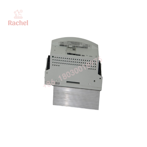
KSD1-16
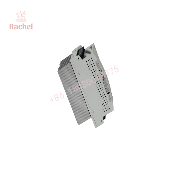
KSD1-16
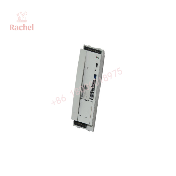
KSD1-16
Field Application & the “Trench” Experience
A KSD1-16 failure can stop an entire robot even though the controller computer, teach pendant, and other servo drives remain operational.
For example, a KRC2 robot may report an axis-drive fault during startup. The natural assumption is that the motor or encoder has failed. But the problem can originate in the KSD1-16 power stage, current feedback, thermal protection, drive communication, or intermediate-circuit section.
A disciplined troubleshooting sequence is therefore:
- Record the exact KRC2 diagnostic code.
- Identify the affected axis.
- Check motor and encoder cabling.
- Inspect the KSD1-16 status indicators.
- Verify the DC intermediate circuit.
- Check drive-bus communication.
- Compare the affected drive with another axis where appropriate.
- Test or replace the KSD1-16 only after the external causes have been excluded.
The KSD1 modules perform current control, commutation, motor-current monitoring, short-circuit protection, heat-sink temperature monitoring, and communication monitoring.
Typical Applications
- KUKA KRC2 six-axis robots
- Robotic welding cells
- Material-handling robots
- Automotive production equipment
- Assembly robots
- External-axis applications
- Legacy KUKA robot controller refurbishment
Transparency SOP: QA & Testing
For New Surplus or Refurbished KSD1-16 inventory, a visual inspection is not enough.
Step 1 — Identity Check
Record:
KUKA- KUKA article number
- Hardware revision
- Serial number
- Drive version
- Robot/controller model
The article number should be compared against the customer’s removed unit. KSD1-16 examples with 00-105-350 and 00-122-285 are documented in the field.
Step 2 — Physical Inspection
Inspect:
- DC-link terminals
- Motor terminals
- InterBus connectors
- PCB connectors
- Heat sink
- Cooling fan/airflow
- Power semiconductor area
- Capacitors
- Signs of overheating or contamination
Step 3 — Electrical Test
Using an appropriate KUKA test system:
- Verify power-up.
- Check diagnostic LEDs.
- Verify drive-bus communication.
- Test current-control behavior.
- Confirm thermal monitoring.
- Check output switching under controlled conditions.
Step 4 — Load Test
The strongest acceptance test is operation on a compatible KRC2 test stand with an appropriate motor/load. Industrial repair providers specifically advertise dedicated KUKA test stands and functional/load testing for KSD1-16 units.
The Veteran’s Tech Trap Guide
⚠️ Trap #1 — Assuming every KSD1-16 has identical electrical data.
Different KSD1-16 versions are documented with different nameplate values, including approximately 565/675 VDC and 585 VDC input examples.
Use the actual nameplate and KUKA article number when qualifying the replacement.
⚠️ Trap #2 — Confusing rated current with maximum current.
KSD1-16 is associated with 8 A rated current and 16 A maximum acceleration current in KUKA technical documentation.
It is not simply an “8 A drive” or a “16 kW drive.”
⚠️ Trap #3 — Assuming KSD1-16 can automatically replace KSD1-08.
A field-maintenance discussion notes that changing drive sizes can require corresponding KUKA controller configuration changes.
Do not make a drive substitution based solely on physical fit or current capacity.
⚠️ Trap #4 — Ignoring the KUKA article number.
KSD1-16 units with different article numbers, including 00-105-350 and 00-122-285, exist. Field-service discussions indicate hardware revisions can differ even when the functional designation remains KSD1-16.
PRO TIP: Put the complete identification into the RFQ:
KUKA KSD1-16 — exact article number and hardware revision to match installed KRC2 drive; provide tested unit with documented load test.
Dynamic FAQ
What is KUKA KSD1-16?
It is a KUKA KRC2 servo drive module used to control an individual robot-axis motor.
What is the rated current?
KUKA technical documentation identifies the KSD1-16 with an 8 A rated current and 16 A maximum acceleration current.
What is the DC-link voltage?
KUKA documentation lists an intermediate-circuit voltage of 0–740 VDC for the KSD1-16. Some aftermarket documentation gives 0–770 VDC, so the actual nameplate/revision should be used for a replacement specification.
Which KUKA controllers use KSD1-16?
The KSD1-16 is primarily associated with the KUKA KRC2 controller family.
What are the KUKA article numbers?
Documented KSD1-16 examples include 00-105-350 and 00-122-285.
Can I replace KSD1-08 with KSD1-16?
Do not assume a direct drop-in replacement. Even where the drive hardware can operate in the same controller family, the robot’s drive configuration and motor parameters must be appropriate for the replacement.
Is a refurbished KSD1-16 a reasonable spare?
Yes. For legacy KRC2 systems, tested refurbished units are a practical maintenance option. Prefer suppliers that perform KRC2-compatible functional and load testing, rather than a simple power-on check.
What warranty should I request?
For a refurbished KSD1-16, request coverage for DC-link startup, drive-bus communication, motor output operation, current control, fault monitoring, thermal protection, and sustained load operation. A bench power-on test alone is insufficient for a robot servo amplifier.

 Start Chat


