





Description
Product Introduction
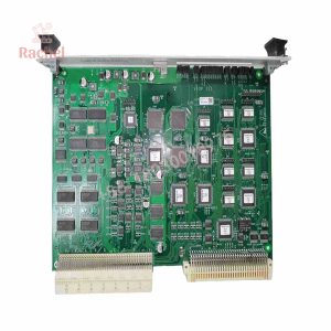
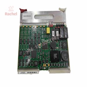
The Lam Research 810-099175-011 VIOP Phase III PCB is an essential vacuum input/output processor board designed for advanced 200mm and 300mm wafer processing platforms, including the Kiyo, Exelan, and 2300 series tool sets. Operating at the core of the tool’s gas and vacuum handling architecture, this board processes real-time telemetry from turbomolecular pumps, throttle valves, pressure transducers, and safety interlocks directly within the chamber enclosure.
Unlike general-purpose industrial I/O boards, the 810-099175-011 VIOP Phase III module features specialized hardware filtering to handle extreme electrical noise generated by high-power RF plasma generators. By executing localized interlock logic at the board level, it protects delicate chamber components from over-pressurization and prevents process gas cross-contamination during complex step execution.
Key Technical Specifications
| Parameter | Value |
| Manufacturer | Lam Research |
| Part Number | 810-099175-011 |
| Board Type | Vacuum Input/Output Processor (VIOP) Phase III |
| Tool Compatibility | Kiyo, Exelan, Vector, 2300 Series Etch Platforms |
| Power Supply Requirements | 24V DC Backplane / Auxiliary Bus |
| Signal Processing | Mixed Digital/Analog Chamber Sensing & Control |
| Form Factor | Multi-Layer High-Density Chassis Card |
| Operating Temperature | 0°C to +55°C (Internal Rack Environment) |
| Operating Humidity | 5% to 85% non-condensing |
Application Scenarios & The “Trench” Experience
Picture this: You are the lead equipment engineer managing a 300mm etch bay during a high-volume production run. Suddenly, Chamber B drops mid-recipe with an erratic “Vacuum Interlock Open” alarm, dumping a fully loaded wafer boat and tripping safety interlocks. Swapping pressure sensors doesn’t fix it; the real culprit is a cracked solder trace under a bus driver chip on the VIOP Phase III board. In a high-throughput fab, every hour of unscheduled tool downtime burns thousands of dollars in unfulfilled wafer allocations.
- Conductor & Dielectric Etch Tools (Kiyo / Exelan) – Manages high-speed communication between throttle valve controllers, baratron pressure gauges, and the main tool controller.
- Gas Box & Load Lock Manifolds – Coordinates multi-valve actuation timing to ensure safe purging, venting, and pump-down sequences.
- Safety Hardware Interlocks – Hardwires critical pressure thresholds to prevent plasma ignition when vacuum levels drift outside tight process windows.
Field Replacement Case: A major semiconductor plant in Oregon faced recurring, non-reproducible vacuum fault aborts on a 2300 series tool. Oscilloscope diagnostics revealed thermal drift on the old VIOP card’s analog comparator circuit. Installing a clean, tested 810-099175-011 replacement restored stable baseline readings instantly, bringing the chamber back to full production clearance in under 40 minutes.
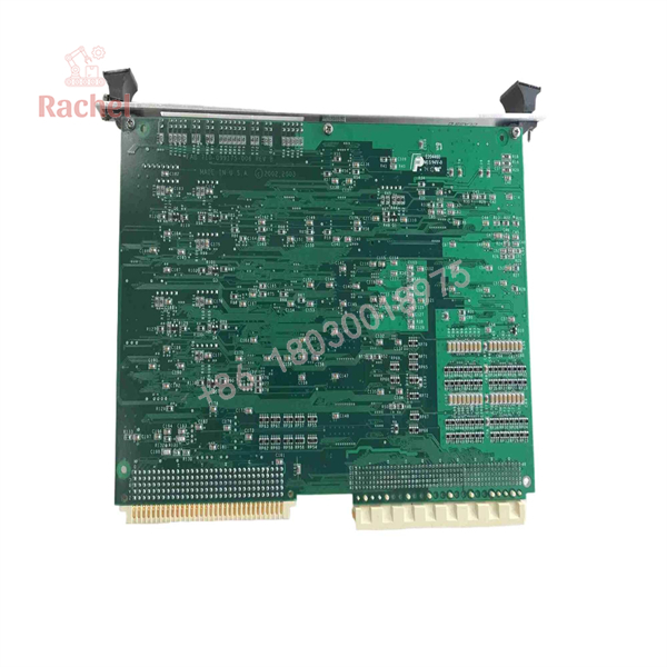
810-099175-011
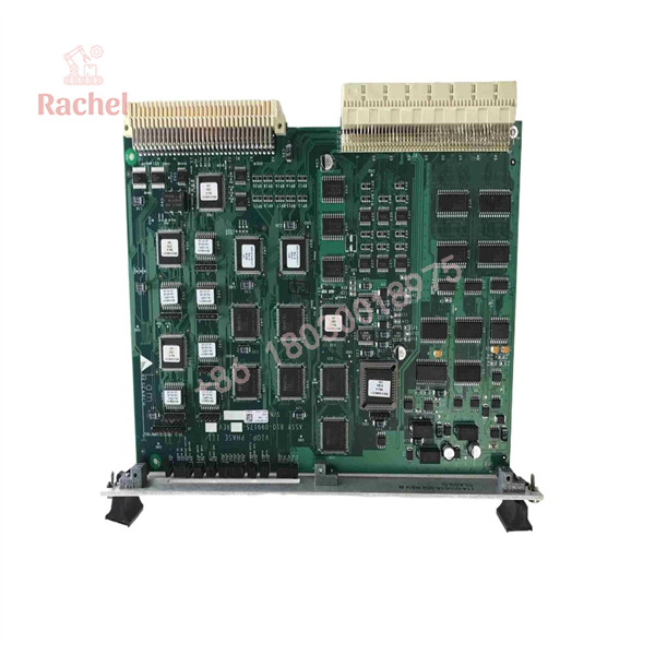
810-099175-011
Transparency SOP: Quality Assurance & Testing
We don’t just ship boxes; we test them on dedicated test benches before signing off for shipment:
- Inbound Visual Inspection: Check under stereo magnification for PCB trace delamination, burnt components, cold solder joints, or damaged connector pins.
- Power-Rail & Thermal Scan: Apply 24V DC bench power to measure baseline current draw and scan for leaky capacitors or thermal anomalies using FLIR imaging.
- Signal Line Driver Verification: Test digital line drivers and optocouplers using logic analyzers to ensure clean switching profiles without ringing or signal droop.
- I/O Loop Simulation: Inject controlled 0-10V analog and 24V digital signals into input pins to verify onboard ADC accuracy and logic execution under load.
- Anti-Static Packaging: Flush backplane edge connectors with electrical contact cleaner, seal the module in a heavy-duty conductive ESD shield bag, and secure it inside high-density custom foam shipping boxes.
The Veteran’s Tech Trap Guide (Crucial Value-Add)
- ⚠️ Match Suffix Revisions Carefully: Pay close attention to the dash number (e.g.,
-011vs.-013). Lam sometimes modifies onboard FPGA logic or analog amplifier gains between revisions; mixing dash numbers can lead to calibration errors in pressure readings. - ❗ De-energize System Power First: Pulling a VIOP card while the 24V DC backplane is live can create inductive arc spikes across edge connectors. Always shut down power to the bay card cage before seating or extracting this module.
- ⚠️ Check Backplane Pin Alignment: The dense multi-pin backplane connectors on Phase III boards can bend easily if inserted at an angle. Never force the board; line up the card guides and seat it using firm, even thumb pressure on the ejector handles.
- ❗ Verify Ground Strap Continuity: Stray RF noise from the tool’s match networks will couple into high-impedance analog sensor lines if the PCB card cage ground strap is loose or corroded. Make sure ground connections are clean and torqued down.
Frequently Asked Questions (FAQ for Conversion)
Q: Is the 810-099175-011 board hot-swappable?
A: No. Pulling this module live risks arcing the backplane connector and causing voltage spikes that can corrupt adjacent cards in the rack. Power down the system rack before swapping.
Q: Does this card require field firmware flashing upon installation?
A: Typically no. The board functions primarily as a hardware-level signal interface. Once installed in a matching system slot, the main tool host controller automatically initializes communication with the card during boot up.
Q: What is the difference between VIOP Phase II and Phase III boards?
A: Phase III boards (like the 810-099175-011) feature updated component density, improved signal isolation against RF noise, and faster response times for high-speed digital interlocks compared to older Phase II modules.
Q: Why buy New Surplus or Refurbished over ordering directly from the OEM?
A: Legacy tool parts from the OEM often carry long lead times—sometimes stretching to months. Our pre-tested surplus stock ships immediately, keeping your production line moving without waiting on OEM manufacturing cycles.
Q: What warranty comes with this module?
A: We back all our 810-099175-011 units with a standard 12-month replacement warranty. If the card fails during normal operation within 365 days of installation, we will replace it or refund your order.

 Start Chat


