





Description
Core Product Summary (Brand / Model / Key Attributes)
The Lenze ESMD113L4TXH509 is an 11 kW SMD-series frequency inverter for variable-speed control of three-phase AC induction motors. It is a 400 V-class Lenze smd drive intended for industrial machinery applications such as conveyors, fans, pumps, and general material-handling equipment.
The ESMD113L4TXH509 converts a fixed-frequency three-phase supply into adjustable output voltage and frequency. The SMD platform provides V/f control with selectable linear or square-law characteristics, acceleration and deceleration ramps, DC-injection braking, PI process control, fixed setpoints, and configurable digital and analog I/O. Parameters are stored in the removable Electronic Programming Module (EPM), and the drive supports RS-485 serial communication through LECOM or Modbus depending on the selected control configuration.
Key Technical Specifications
| Attribute | Value |
|---|---|
| Brand | Lenze |
| Model | ESMD113L4TXH509 |
| Product family | Lenze smd frequency inverter |
| Rated power | 11 kW |
| Input supply | Three-phase 400/480 V AC |
| Input voltage range | 320 V AC −0% to 528 V AC +0% |
| Input frequency | 50/60 Hz, 48 Hz −0% to 62 Hz +0% |
| Output voltage | 0–400 / 0–460 V AC |
| Output frequency | 0–500 Hz |
| Comparable ESMD113L4TXA rating | 24 A continuous at 400 V; 21 A continuous at 480 V |
| Comparable 60-second overload rating | 36 A at 400 V; 32 A at 480 V |
| Control modes | V/f control; linear or square-law characteristic |
| Braking functions | DC-injection braking; dynamic-braking option support |
| Process control | PI control with configurable feedback and setpoints |
| Analog input | 0–10 V, 0–5 V, 0–20 mA, 4–20 mA, or monitored 4–20 mA |
| Analog output | 0–10 V DC, scalable |
| Digital inputs | Start/stop plus three configurable inputs E1–E3 |
| Digital output | Configurable NPN output, 24 V DC / 50 mA |
| Relay output | Configurable form-A relay; 250 V AC / 3 A or 24 V DC / 2 A to 240 V DC / 0.22 A |
| Serial communication | RS-485; LECOM or Modbus depending on configuration |
| Parameter storage | Removable Electronic Programming Module (EPM) |
| Enclosure protection | IP20 |
| Operating temperature | 0 to 55 °C, with 2.5%/°C current derating above 40 °C |
| Storage temperature | −20 to 70 °C |
| Transport temperature | −25 to 70 °C |
| Maximum installation altitude | 4,000 m, with current derating above 1,000 m |
| Humidity | Below 95%, non-condensing |
| Motor cable length | 50 m shielded low-capacitance; 100 m unshielded |
| Approvals | CE; UL 508C |
| Manual | Lenze smd Operating Instructions, SL03 |
Detailed Product Overview
The Lenze ESMD113L4TXH509 is an SMD-series AC frequency inverter rated at 11 kW for three-phase 400/480 V motor-control applications. It regulates motor speed by varying output voltage and frequency, making it suitable for standard induction-motor drives where speed, torque, starting behavior, and process feedback must be managed by the drive.
The SMD platform uses V/f control rather than closed-loop servo control. For standard machinery loads, the linear V/f characteristic with Auto-Boost provides load-dependent output voltage at low speed. For fans and centrifugal pumps, the square-law characteristic reduces energy demand at reduced speed. The drive also provides slip compensation, acceleration boost, adjustable current limit, and selectable carrier frequency from 4 to 10 kHz.
Control flexibility is a central feature of the ESMD113L4TXH509. The start/stop input, three configurable digital inputs, analog setpoint input, analog output, digital output, and relay output allow integration with conventional pushbuttons, selector switches, PLC I/O, motor thermal contacts, and process instrumentation. The drive can be controlled locally, through terminals, through an optional remote keypad, through LECOM, or through Modbus. RS-485 communication uses terminals 71 and 72.
Parameter settings are retained in the removable EPM. This allows drive configuration to be transferred or replaced without reproducing every parameter manually, provided the EPM contains valid data for the drive. An optional EPM Programmer, model EEPM1RA, supports off-line programming, OEM default settings, and copying parameter files across multiple drives.
Installation requires attention to EMC, cooling, and supply quality. The drive is intended for cabinet mounting on a conductive plate, with appropriate shielding, grounding, filters, and cable routing. The manufacturer specifies that IT power systems are not supported and that input-power cycling should not occur more often than once every three minutes.
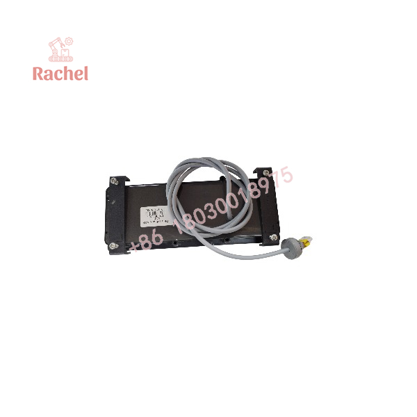
ESMD113L4TXH509
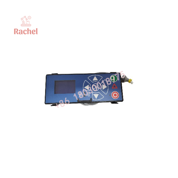
ESMD113L4TXH509
Engineering Selection Highlights
- The ESMD113L4TXH509 is an 11 kW, 400/480 V three-phase SMD inverter, so the connected motor and supply transformer must match this voltage class and power requirement.
- It uses V/f control for standard AC induction motors, rather than resolver-based servo control; confirm that the application does not require closed-loop position control.
- The EPM stores drive parameters and can be removed, so preserving or transferring the EPM is important during drive replacement or configuration management.
- The drive provides terminal, remote-keypad, LECOM, and Modbus control options, allowing selection of the appropriate control architecture during commissioning.
- Its configurable digital inputs support jog, direction, DC braking, quick stop, trip, trip reset, and ramp selection, so the required machine interlocks and operator controls should be mapped before installation.
- The PI function accepts process feedback on the analog input, enabling pressure, flow, temperature, or other process-variable control where the feedback signal is compatible with the drive input.
- Cabinet installation must address EMC and thermal conditions, including shielded motor cable, grounding, filters where required, and current derating above 40 °C or 1,000 m altitude.
System Compatibility & Integration Requirements
| Item / Dependency | Verified Compatibility or Requirement | Practical Note |
|---|---|---|
| Motor type | Three-phase AC induction motor | The SMD inverter provides variable-frequency V/f control. |
| Supply system | Three-phase 400/480 V AC, 320–528 V AC range | Confirm supply voltage and phase balance before energizing. |
| Supply system restriction | IT mains systems are not supported | Use an appropriate TN or TT supply arrangement. |
| Motor cable | Maximum 50 m shielded low-capacitance or 100 m unshielded | EMC compliance may require shorter cable lengths or additional filtering. |
| Control interface | Terminals, remote keypad, LECOM, or Modbus | Select the control source using parameter C01. |
| Serial network | RS-485 at terminals 71 and 72 | Assign a unique network address to each controller. |
| Parameter storage | EPM must be installed for drive operation | A missing or invalid EPM prevents normal operation. |
| Programming accessory | Optional EPM Programmer EEPM1RA | Supports off-line programming and parameter-file copying. |
| Dynamic braking | Requires the appropriate braking option | Use for applications with regenerative deceleration; verify resistor thermal capacity. |
| Enclosure | IP20 drive; install in a suitable cabinet | Protect against dust, moisture, oil mist, vibration, and excessive temperature. |
Dimensions, Mounting & Connection Notes
For the comparable ESMD113L4TXA 11 kW 400 V SMD frame, Lenze documents the following mechanical data:
| Attribute | Value |
|---|---|
| Housing width | 146 mm |
| Mounting-hole spacing, width | 137 mm |
| Housing height | 197 mm |
| Mounting-hole spacing, height | 140 mm |
| Depth | 182 mm |
| Side clearance | 30 mm |
| Vertical clearance | 100 mm |
| Mass | 3.2 kg |
| Mounting hardware | Four M6 screws |
| Mounting-screw torque | 2.8 Nm / 24 lb-in |
- Mount the inverter vertically on an electrically conductive mounting plate.
- Maintain 30 mm side clearance and 100 mm clearance above and below the unit.
- Use shielded, low-capacitance motor cable where EMC performance is required; use the supplied screen clamps and maintain separation between power and control wiring.
- Power terminals require up to 6 mm² / AWG 8 input wiring; control terminals accept conductors as small as 1 mm² / AWG 26.
- For the comparable 11 kW 400 V model, Lenze recommends a 40 A fuse or C40 A miniature circuit breaker, with 6 mm² input power wiring.
- Do not connect mains power to output terminals U, V, and W.
- After disconnecting supply power, wait until the DC bus voltage between B+ and B− is 0 V DC before servicing.
FAQ
What is the Lenze ESMD113L4TXH509?
It is an 11 kW Lenze SMD-series frequency inverter for variable-speed control of three-phase AC induction motors.
What supply voltage does the ESMD113L4TXH509 use?
It is a 400/480 V AC-class drive, with a documented SMD 400 V input range of 320 V AC to 528 V AC.
What type of motor control does it provide?
It provides V/f control, with linear or square-law voltage-frequency characteristics, rather than closed-loop servo position control.
Does it support communications?
Yes. The SMD platform provides RS-485 serial communication and can be configured for LECOM or Modbus communication.
How are parameters stored?
Parameters are stored in the removable Electronic Programming Module (EPM). The EPM must be installed for the drive to operate.
Can the drive be used for PID or process control?
Yes. It includes a PI function with configurable setpoint, feedback, proportional gain, integral gain, and feedback alarm limits.
What braking options are available?
The drive supports DC-injection braking and can be used with the appropriate dynamic-braking option for regenerative loads.
What environmental limits apply?
The drive operates from 0 to 55 °C, with current derating above 40 °C, and must be installed in a suitable cabinet because the drive itself is IP20.
Verification & Troubleshooting Notes
- Confirm the complete nameplate, including type , ID number, input/output ratings, hardware version, and software version.
- Verify that the EPM is installed and contains data valid for the drive; an EPM data error, OEM-data error, or missing EPM will prevent normal operation.
- If the drive remains stopped, check terminal 28: a LOW signal means stop and inhibited output; a HIGH signal is required for run enable.
- If the drive is set for remote keypad, LECOM, or Modbus control, local keypad start commands may be disabled; check parameter C01.
- For a 4–20 mA reference fault, verify that the analog signal remains above 2 mA when parameter C34 is set to monitored 4–20 mA mode.
- For overcurrent or earth-fault indications, inspect the motor cable, motor insulation, output wiring, cable capacitance, acceleration ramp, and drive sizing.
- For DC-bus overvoltage, check supply voltage, deceleration time, regenerative load behavior, and whether dynamic braking is required.
- Do not cycle input power more than once every three minutes; repeated power cycling can damage the drive.
- Do not use the drive on an IT supply system, and do not bypass grounding, shielding, or protective-earth requirements.

 Start Chat


