





Description
Product Introduction & Engineering Value
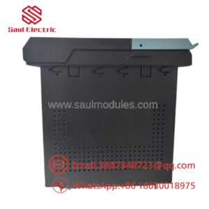
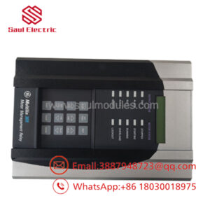
The GE Multilin MIFIIPI55E00HI00 is a compact, digital feeder protection relay designed for primary protection in distribution networks and backup protection for transformers, generators, and MV motors. Operating as part of the Multilin MIF II family, it consolidates phase/ground overcurrent protection, breaker control, and monitoring into a single flush-mount enclosure.
By combining inverse-time and instantaneous overcurrent elements (ANSI 50/51/50N/51N) with event logging and Modbus serial communications, the MIF II replaces multiple electromechanical relays. Its high-range auxiliary power supply module (HI) allows flexible deployment across both AC and DC control buses without requiring external step-down converters.
Part Number Decoder & Technical Specifications
Part Number Breakdown: MIF II - P - I55 - E - 00 - HI - 00
MIF II: Model Family (Multilin Feeder Protection Relay)P: Protection Functionality (Phase and Ground Overcurrent Protection)I55: Current Inputs — 5A Phase CT / 5A Ground CTE: Display Language — English LCD & Interface00: Standard Hardware Option / Reserved Base FeatureHI: Auxiliary Power Supply — High Voltage Range (63–240 VDC / 88–250 VAC)00: Standard Firmware & Options
Key Technical Specifications
- Protection Elements:
- Phase Time Overcurrent (ANSI 51) & Instantaneous Overcurrent (ANSI 50)
- Ground Time Overcurrent (ANSI 51N) & Instantaneous Overcurrent (ANSI 50N)
- Frequency: 50/60 Hz Auto-sensing
- CT Ratings: 5A nominal inputs (Continuous current thermal withstand: 2x nominal)
- Output Contacts: Configurable Trip and Control Relays (Form A / Form C)
- Digital Inputs: Optically isolated status inputs for external interlocks or reset
- Communication Port: Front RS232 port for PC software setup; Rear RS485 port supporting Modbus RTU protocol
- Enclosure: Compact draw-out or panel flush-mount design
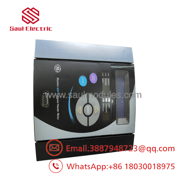
- MIFIIPI55E00HI00
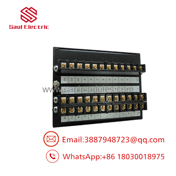
- MIFIIPI55E00HI00
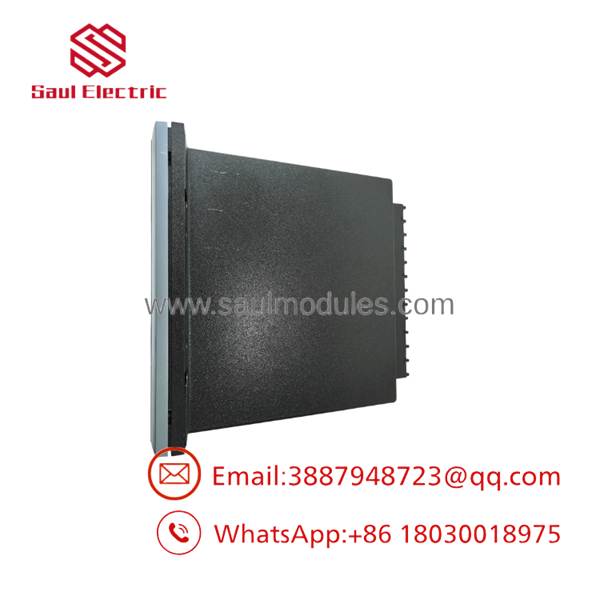
- MIFIIPI55E00HI00
Field Application & The “Trench” Experience
During a retrofitting project at a steel manufacturing plant, an engineering team replaced an aging disk-type electromechanical protection relay on a 13.8kV feeder breaker that was prone to false trips from vibration. Space inside the switchgear door was tight. The MIFIIPI55E00HI00 was selected because its compact footprint fitted into the existing cutout with minimal panel modification.
Connected to standard 5A CT secondaries and powered directly from the station’s 125 VDC battery system (HI rating), the relay provided immediate event-recording capability. When a downstream cable faulted weeks later, the relay’s front LCD provided instant trip magnitude data and time-stamping, cutting line troubleshooting down from hours to minutes.
Niche Application Scenarios:
- Distribution Feeder Protection: Primary overcurrent/earth fault protection on medium-voltage radial networks.
- Transformer Backup Protection: Secondary-side backup against sustained external fault currents.
- Industrial Motor Feeder Protection: Overcurrent protection for direct-on-line MV motor starters.
Transparency SOP: QA & Testing
- Visual & Mechanical Inspection: Casing, terminals, keypad membrane, and draw-out contacts are checked for physical wear, bent terminal pins, or heat discoloration.
- Auxiliary Power Ramp Test: High-voltage power supply (
HI) is energized across its operating range (88–250 VAC / 63–240 VDC) to verify clean bootup without power supply ripple. - 5A Current Injection Calibration: Secondary current is injected into the 5A phase and ground CT inputs using a secondary injection test set to verify pickup thresholds, timing curves, and measurement accuracy within ±1%.
- Output Relay & Trip Logic Test: Trip and alarm contacts are exercised under simulated fault conditions to confirm contact resistance (< 0.1 ohms) and instantaneous response times.
- Serial Communication Check: Modbus RTU communications over the rear RS485 port are polled to ensure stable telemetry transmission.
The Veteran’s Tech Trap Guide
- ⚠️ CT Rating Verification (
I55vs.I11): Ensure your instrument transformers provide 5A secondaries. Installing thisI55unit (5A Phase / 5A Ground) on a 1A CT secondary loop will result in under-sensing and a failure to trip during genuine fault conditions. - PRO TIP (Front Port Setup): Use GE’s EnerVista or MIF II setup software via the front RS232 port for fast curve selection (IEEE, IEC, or IAC curves). Downloading settings via software prevents manual keypad configuration errors on time-dial multipliers.
- ⚠️ Control Power Voltage Range: Confirm your auxiliary supply matches the
HIrating (63–240 VDC / 88–250 VAC). Applying low-voltage control power (like 24 VDC) to anHImodel will cause the relay to remain powered off or reset continuously under load.
Dynamic FAQ
Q: What is the power supply voltage range for the HI option on the MIFIIPI55E00HI00?
A: The HI option accepts 63 to 240 VDC or 88 to 250 VAC, making it suitable for standard 110/125/220V station battery systems or AC auxiliary buses.
Q: Can this relay communicate with a plant DCS or SCADA system?
A: Yes. The rear RS485 port supports Modbus RTU protocol for remote metering, status monitoring, and event retrieval by a central SCADA or DCS network.
Q: Does the support both IEEE and IEC time-overcurrent curves?
A: Yes. The firmware includes standard inverse, very inverse, extremely inverse, and definite time curves compliant with ANSI/IEEE and IEC standards.


 Start Chat


