





Description
Core Product Summary (Brand / Model / Key Attributes)
The Moog G122-829A-001 (also designated G122-829A001) is a general-purpose, user-configurable P-I (proportional-integral) servo amplifier designed for closed-loop control of electro-hydraulic servo valves.
Internal selector switches allow the unit to operate in proportional (P), integral (I), or combined P&I mode. Front-panel potentiometers and internal switches provide extensive adjustment of gains, inputs, and output characteristics, enabling one amplifier to serve a wide range of positioning, pressure, and velocity control applications. The amplifier mounts on a standard DIN rail and operates from a 24 V DC supply.
Key Technical Specifications
| Parameter | Specification |
|---|---|
| Product Type | User-configurable P-I servo amplifier |
| Manufacturer | Moog |
| Model | G122-829A-001 / G122-829A001 |
| Control Modes | P, I, or P & I (switch selectable) |
| Supply Voltage | 24 V DC (typically 22–28 V) |
| Mounting | DIN rail |
| Dimensions (W × H × D) | approx. 100 × 108 × 45 mm |
| Weight | approx. 180 g |
| Command / Feedback Inputs | ±10 V and 4–20 mA (switch selectable) |
| Output Options | ±10 V, current (up to ±100 mA), or 4–20 mA |
| Protection Class | IP20 |
| Operating Temperature | 0 to +40 °C (typical) |
Detailed Product Overview
The Moog G122-829A-001 is an analog servo amplifier intended for closed-loop electro-hydraulic control systems. It accepts command and feedback signals, generates an error signal, and processes that error through selectable proportional and/or integral stages before driving a servo valve.
Three primary inputs (two single-ended and one differential) plus a dedicated feedback input support both voltage (±10 V) and current (4–20 mA) signals. The amplifier includes a feedback amplifier with adjustable zero and gain, optional derivative (velocity) feedback, and a +10 V transducer excitation supply.
The output stage is switch-selectable for voltage (±10 V), current drive (up to ±100 mA in selectable ranges), or 4–20 mA. Additional features include an enable input, adjustable dither, front-panel LEDs and test points for commissioning, and internal configuration switches that allow the unit to be adapted to many different loop structures without external components.
The compact DIN-rail housing makes the amplifier suitable for installation in industrial control cabinets. It is commonly used to drive Moog and other manufacturers’ servo valves in precision positioning, pressure control, and velocity control systems.
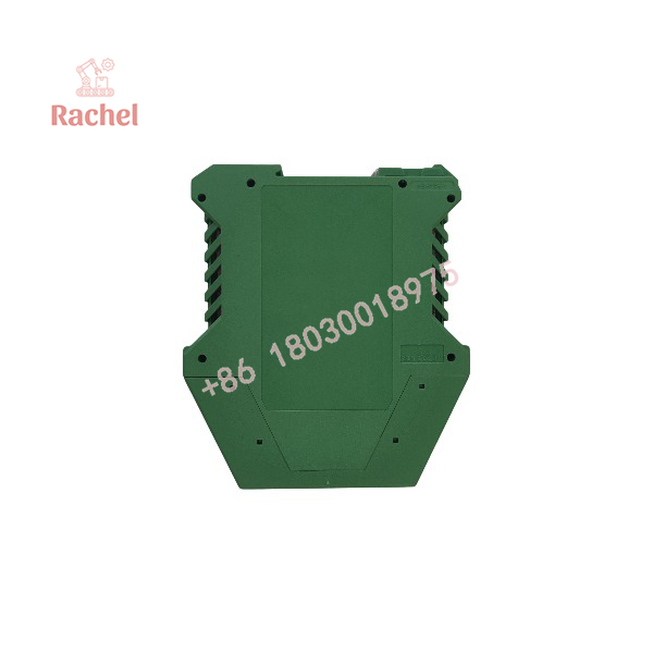
G122-829A-001
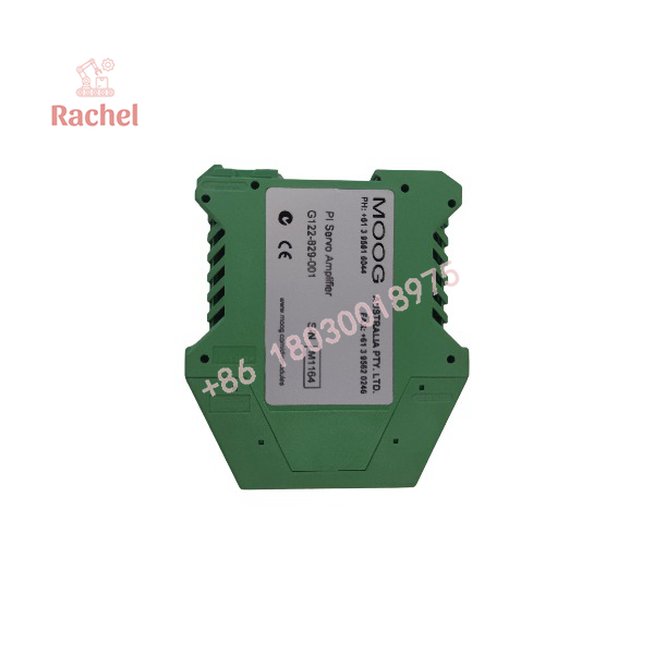
G122-829A-001
Engineering Selection Highlights
- Switch-selectable P, I, or P&I control → flexible closed-loop structure.
- Multiple input types (±10 V and 4–20 mA) → compatible with common industrial sensors and controllers.
- Configurable output (voltage, current, or 4–20 mA) → drives a wide range of servo valves.
- Front-panel pots and LEDs → simplifies setup and troubleshooting.
- Internal configuration switches → one amplifier adapts to many applications.
- DIN-rail mounting → standard industrial cabinet installation.
- Transducer excitation supply → supports active feedback sensors.
- Compact size and low weight → efficient use of panel space.
Dimensions, Mounting & Connection Notes
- Dimensions: approximately 100 mm (W) × 108 mm (H) × 45 mm (D)
- Weight: approximately 180 g
- Mounting: DIN rail (rail release clip facing down recommended)
- Connections: Screw terminals for power, inputs, feedback, and valve output
- Front panel: Adjustment pots, LEDs, and test points
Exact terminal assignments, switch settings, and recommended configuration procedures are detailed in the official Moog G122-829A001 Application Notes and data sheet.
System Compatibility & Integration Requirements
| Item / Dependency | Verified Compatibility or Requirement | Practical Note |
|---|---|---|
| Power Supply | 24 V DC (22–28 V typical) | Standard industrial control voltage |
| Command Signals | ±10 V or 4–20 mA | Switch selectable |
| Feedback Signals | ±10 V or 4–20 mA | Differential input with adjustable gain |
| Output to Valve | ±10 V, current up to ±100 mA, or 4–20 mA | Matches most Moog and third-party servo valves |
| Mounting | DIN rail | Horizontal rail preferred for cooling airflow |
| Configuration | Internal switches + front-panel pots | Refer to Moog application notes for recommended settings |
| Related Documentation | Data sheet G122-829 and Application Notes | Essential for correct setup |
FAQ
What is the Moog G122-829A-001?
It is a user-configurable proportional-integral (P-I) servo amplifier used to drive electro-hydraulic servo valves in closed-loop control systems.
What control modes does it support?
Proportional (P), integral (I), or combined P&I, selected by internal switches.
What power supply is required?
24 V DC (typically in the 22–28 V range).
What input and output signals are supported?
Inputs accept ±10 V and 4–20 mA. Outputs can be configured as ±10 V, current (up to ±100 mA), or 4–20 mA.
How is the amplifier mounted?
On a standard DIN rail inside an industrial control enclosure.
Where can configuration details be found?
In the Moog G122-829 data sheet and the G122-829A001 Application Notes.

 Start Chat


