





Description
Technical Specifications
| Specification | 8206-TI-IS |
|---|---|
| Manufacturer | MTL Instruments |
| Product Family | MTL8000 2/1 I/O |
| Module Type | 8-channel IS RTD / resistance input |
| Number of Channels | 8 |
| Input Type | RTD and Ω |
| RTD Connection | 2-, 3-, or 4-wire |
| Channel Configuration | Independently configurable |
| RTD Excitation | 211 µA nominal |
| Excitation Compliance Voltage | 6.8 V |
| Resolution | 16 bits |
| Series-Mode Rejection | >50 dB at 50/60 Hz |
| Channel-to-Railbus Isolation | 60 V peak |
| Module Key Code | C3 |
| Module Width | 42 mm |
| Approx. Weight | 245 g |
| Recommended Field Terminal | 8626-FT-IS |
The core electrical values above are from the MTL 8206-TI-IS datasheet.
Intrinsic-Safety Architecture
The 8206-TI-IS uses eight separate intrinsically safe field circuits. The IECEx certificate describes the module as having eight galvanically isolated and independent intrinsically safe circuits, with the field-side connections made through the certified 8626-FT-IS RTD field terminal.
The Factory Mutual approval likewise specifies that the 8206-TI-IS must be installed with the 8626-FT-IS field terminal and within an approved PAC8000 Series I/O system associated IS apparatus.
How the 8206-TI-IS Measures RTDs
The module supplies a small excitation current to the RTD and measures the resulting resistance. The measured resistance is then converted into temperature data for the control system.
A simplified signal path is:
RTD in Hazardous Area → 8626-FT-IS → 8206-TI-IS → MTL8000 Railbus → Control System
The 211 µA nominal excitation current and 16-bit conversion resolution are particularly relevant when evaluating the module for precision temperature measurement.
2-Wire, 3-Wire, and 4-Wire RTD Support
One of the practical advantages of the 8206-TI-IS is its support for different RTD wiring configurations.
2-Wire RTD
The simplest arrangement, but lead resistance contributes directly to the measured resistance. This can introduce a noticeable temperature error on long cable runs.
3-Wire RTD
Common in industrial process instrumentation because it compensates for lead resistance more effectively than a basic 2-wire arrangement.
4-Wire RTD
Provides the highest level of lead-resistance compensation and is useful where measurement accuracy is more important than wiring simplicity.
The actual wiring configuration must match the configured channel parameters. MTL explicitly specifies 2-, 3-, and 4-wire RTD capability for the 8206-TI-IS.
Field Application & Trench Experience
Hazardous-Area Reactor Temperature Monitoring
Consider a chemical plant with multiple RTDs installed around a reactor and associated process equipment. Eight temperature loops can be brought into one 8206-TI-IS while maintaining intrinsically safe field circuits.
During replacement, the engineer should record the existing:
- RTD type.
- Wiring configuration.
- Channel assignment.
- Temperature range.
- Engineering-unit scaling.
- Alarm limits.
- Open-circuit behavior.
- Field-terminal configuration.
The most common commissioning mistake is to replace the hardware correctly but configure the channel for the wrong RTD wiring arrangement.
Other Application Scenarios
Refinery Temperature Monitoring
Process vessels, distillation equipment, heat exchangers, and hazardous-area piping.
Chemical Processing
Reactor and storage-vessel temperature measurement where RTDs are installed inside classified areas.
Oil & Gas Facilities
Temperature monitoring around pumps, separators, compressors, and process skids.
Tank Farms
Multiple RTDs can be consolidated into a distributed I/O architecture while retaining intrinsically safe field circuits.
QA & Testing SOP
1. Part Identification
Verify:
- MTL Instruments marking
- Exact model 8206-TI-IS
- Serial number
- Module revision
- C3 key code
- Physical connector arrangement
Do not confuse 8206-TI-IS with 8205-TI-IS. MTL documentation identifies 8205-TI-IS as the thermocouple input module and 8206-TI-IS as the RTD input module.
2. Physical Inspection
Inspect:
- Backplane connector
- Field-side interface
- Module housing
- Keying components
- PCB condition
- Terminal connections
- Signs of corrosion or moisture contamination
3. Resistance Simulation
A proper bench test should use precision resistance sources or RTD simulators to represent several operating points.
For each channel, verify:
- Resistance acquisition
- Temperature conversion
- Channel configuration
- Open-circuit detection
- Fault reporting
4. Wiring Configuration Test
Where possible, test representative:
- 2-wire RTD
- 3-wire RTD
- 4-wire RTD
This is important because a simple resistance-input test does not necessarily prove correct lead-compensation behavior.
5. System-Level Verification
After module-level testing, verify communication through the MTL8000 architecture and confirm that the host control system correctly receives the channel values and diagnostics.
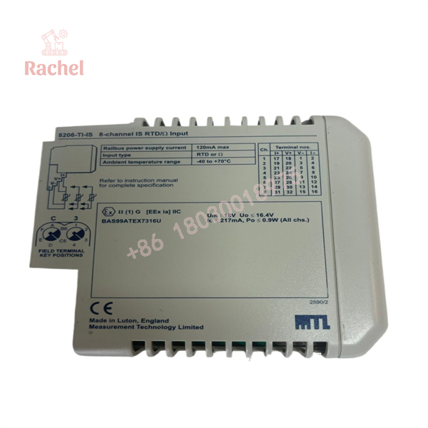
8206-TI-IS
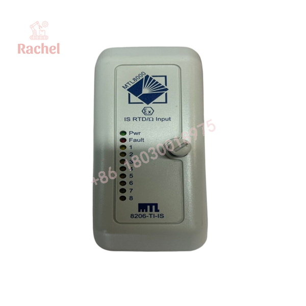
8206-TI-IS
Veteran’s Tech Trap Guide
Trap 1 — 8205-TI-IS vs. 8206-TI-IS
These two part numbers are easy to confuse.
- 8205-TI-IS: Thermocouple input
- 8206-TI-IS: RTD/resistance input
MTL’s IECEx documentation explicitly distinguishes the two modules by their input circuits.
Trap 2 — Forgetting the 8626-FT-IS
The 8206-TI-IS is not simply a standalone DIN-rail temperature card. The certification documentation specifies the 8626-FT-IS as the appropriate RTD field terminal.
When replacing an existing module, verify the complete carrier and field-terminal arrangement.
Trap 3 — Treating 2-Wire and 3-Wire RTDs as Equivalent
They are not electrically equivalent from a measurement-error standpoint. Lead resistance affects a 2-wire measurement directly, whereas 3-wire and 4-wire configurations provide progressively better compensation.
Trap 4 — Confusing RTD With Thermocouple Inputs
A thermocouple generates a small voltage; an RTD changes resistance. The 8206-TI-IS is specifically designed for RTD and Ω measurement, not thermocouple input.
Procurement & Replacement Notes
Before ordering a replacement 8206-TI-IS, compare the complete installation:
- Exact module number
- Carrier model
- Field-terminal model
- RTD type
- 2-/3-/4-wire configuration
- Existing channel assignments
- Hazardous-area certification requirements
- MTL8000 Railbus architecture
- Keying configuration
MTL’s current product documentation index continues to list 8206-TI-IS within its MTL8000 2/1 I/O documentation family.
For an intrinsically safe installation, certification compatibility should be checked from the actual project documentation rather than inferred from a reseller listing. The FM certificate specifically identifies the 8206-TI-IS and its required 8626-FT-IS field-terminal arrangement.
FAQ
What is the MTL 8206-TI-IS?
It is an 8-channel intrinsically safe RTD and resistance input module for the MTL8000 2/1 I/O system.
How many RTD channels does it provide?
The 8206-TI-IS provides 8 input channels, with channels independently configurable.
Does it support 2-wire, 3-wire, and 4-wire RTDs?
Yes. The MTL datasheet specifically lists 2-, 3-, and 4-wire RTD formats.
What is the RTD excitation current?
The specified nominal excitation current is 211 µA, with a 6.8 V compliance voltage for the current source.
What field terminal is required?
The certification documentation specifies the 8626-FT-IS RTD field terminal for the 8206-TI-IS.
Is the 8206-TI-IS a thermocouple input module?
No. The 8205-TI-IS is the MTL8000 thermocouple input module; 8206-TI-IS is the RTD/resistance input module.
How should New Surplus condition be verified?
Request photographs of the actual module, including its nameplate and connectors. For a critical safety-system spare, also request serial/traceability information and functional-test records where available. “New Surplus” should be treated as the seller’s inventory-condition description, not as independent evidence of current factory-new production.

 Start Chat


