





Description
Product Introduction & Engineering Value
The 140SDI95300S is not simply a 16-point replacement for a conventional Quantum DDI card. Its architecture is designed to monitor safety-related field signals and detect conditions that could prevent reliable transmission of the input state to the Quantum safety CPU. Each input channel uses a dedicated interface circuit with two independent input paths, followed by comparison and diagnostic processing.
That distinction matters during replacement. A standard 24 VDC input module may match the voltage and channel count but cannot automatically reproduce the safety architecture, diagnostics, certification, or application assumptions of the 140SDI95300S. Schneider’s current replacement recommendation is BMXSDI1602, but migration requires safety-application engineering rather than a simple hardware swap.
Technical Specifications
| Parameter | Specification |
|---|---|
| Catalog Number | 140SDI95300S |
| Platform | Modicon Quantum |
| Module Type | Safety DC discrete input |
| Number of Inputs | 16 |
| Input Voltage | 24 VDC |
| Input Voltage Range | 19.2–30 VDC sensor supply |
| Logic | Positive logic / sink input |
| Input Groups | 1 group |
| State 1 Guaranteed | 11–30 VDC |
| State 0 Guaranteed | -3–5 VDC |
| State 1 Current | ≥3 mA |
| State 0 Current | ≤1.5 mA |
| Input Impedance | 3,675 Ω |
| Absolute Maximum Input | 30 VDC |
| Addressing Requirement | 7 input words |
| Safety Architecture | Dual independent input paths with comparison and diagnostics |
| Safety Application | IL3 / SIL 2 class applications |
| Sensor Supply | 19.2–30 VDC |
| Approximate Weight | 0.5 kg |
The 7 input-word addressing requirement is particularly important. It reinforces that this is a specialized safety module rather than an ordinary 16-point discrete input card. Schneider’s product data also specifies positive logic and the 11–30 VDC guaranteed ON-state range.
The module’s internal architecture uses two independent input paths per channel, with diagnostic comparison before the resulting state is communicated to the safety CPU.
Field Application & the “Trench” Experience
A legacy machine has a Quantum safety PLC monitoring protective-door switches, emergency-stop circuits, and other safety-related field conditions. One 140SDI95300S begins reporting an input discrepancy.
The technician initially checks the field switch and measures the expected 24 VDC signal. The temptation is to conclude that the input module has failed.
That conclusion is premature.
With a safety input module, the troubleshooting sequence has to account for both input paths, field wiring, reference connections, diagnostic status, and the safety CPU’s interpretation of the module state. A simple voltage measurement at the field device does not prove that the complete safety input channel is healthy.
The technician compares the affected channel against the module’s diagnostics, checks the field circuit at the I/O terminals, reviews the safety application’s expected input behavior, and only then evaluates the module as a potential failure point.
Specific application scenarios:
- Machine guard monitoring: safety-door and protective-gate position feedback.
- Emergency-stop circuits: monitored safety contacts and associated 24 VDC circuits.
- Press and forming equipment: safety interlock feedback and protective-device monitoring.
- Process-unit shutdown systems: discrete permissives and safety-related equipment status.
- Material-handling machinery: safety switches and access-zone monitoring.
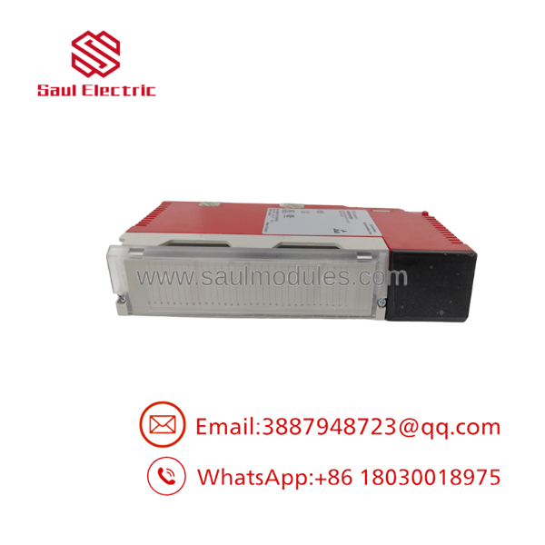
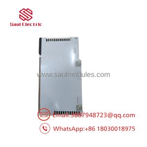
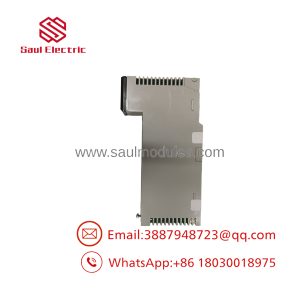
140SDI95300S
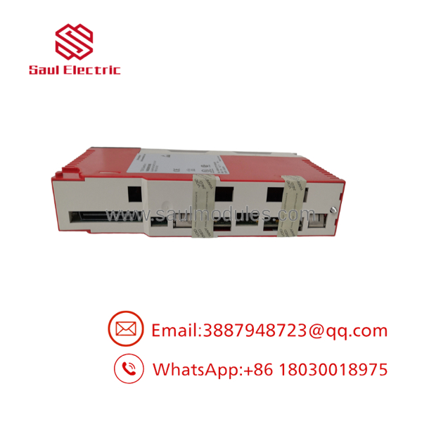
140SDI95300S
Transparency SOP: QA & Testing
For New Surplus or refurbished 140SDI95300S inventory, ordinary digital-input testing is not enough. Safety hardware requires a more disciplined verification approach.
- Part-number verification — Confirm the exact
140SDI95300Scatalog number. - Physical inspection — Examine the housing, connectors, labeling, backplane interface, and status indicators.
- Configuration review — Verify compatibility with the intended Quantum safety architecture.
- Controlled 24 VDC test — Apply appropriate input signals through a protected test fixture.
- Channel verification — Exercise representative inputs across the complete 16-channel section.
- Diagnostic verification — Confirm that expected input states and diagnostic information are correctly reported.
- Dual-path behavior — Where the approved test equipment and procedure permit, verify the module’s channel-monitoring behavior rather than testing only the external input voltage.
- Safety-system integration — Confirm proper communication with an appropriate Quantum safety test system.
- Documentation — Record the test procedure, equipment, channels tested, firmware/configuration information where relevant, and final stock condition.
Important: A supplier should not claim that a refurbished 140SDI95300S is “safety certified” merely because the module powers up and its LEDs illuminate. Certification applies to the defined safety system and application architecture, not simply to a used module sitting on a test bench.
The Veteran’s Tech Trap Guide
⚠️ Trap #1 — Do not replace it with an ordinary 24 VDC input card.
The 140SDI95300S contains safety-specific architecture and diagnostics. Schneider identifies the module as a safety input device and documents its internal dual-path input structure. A conventional Quantum DDI module may have the same nominal voltage but does not provide equivalent safety functionality.
⚠️ Trap #2 — 24 VDC at the sensor does not prove a healthy safety channel.
The guaranteed ON-state range is 11–30 VDC, while the guaranteed OFF-state range is -3 to 5 VDC. If a field circuit sits in the intermediate region, the input state should not be assumed.
PRO TIP: Measure the signal at the module terminal under operating conditions, not only at the safety switch or sensor.
⚠️ Trap #3 — Don’t bypass a safety diagnostic to keep production running.
If the module detects an internal or channel-related discrepancy, forcing an input state in software or bypassing the field circuit can defeat the purpose of the safety architecture. Troubleshoot the actual fault and follow the site’s approved safety procedure.
⚠️ Trap #4 — The recommended replacement is not a plug-in assumption.
Schneider identifies BMXSDI1602 as the recommended replacement. It is a Modicon X80 safety discrete input module with 16 positive-logic 24 VDC inputs. Moving from Quantum to X80 changes the hardware platform and requires verification of the safety controller, rack architecture, configuration, wiring, and application certification.
Dynamic FAQ
Q: What is the Schneider 140SDI95300S?
A: It is a 16-channel, 24 VDC safety discrete input module for the Modicon Quantum platform. It is intended for safety-related input monitoring rather than ordinary PLC digital I/O.
Q: How many inputs does the 140SDI95300S provide?
A: It provides 16 safety discrete inputs in one input group. Schneider’s documentation describes two independent input paths associated with each channel for safety monitoring and diagnostics.
Q: What are the input voltage thresholds?
A: The guaranteed ON-state range is 11–30 VDC, while the guaranteed OFF-state range is -3 to 5 VDC. The module’s specified sensor supply range is 19.2–30 VDC.
Q: What safety level is associated with the 140SDI95300S?
A: Schneider documentation identifies the module among its Quantum safety I/O products certified by TÜV Rheinland for use in an IL3 safety function. Safety performance must still be evaluated as part of the complete safety system and application.
Q: Is the 140SDI95300S discontinued?
A: Yes. Schneider regional product pages show different discontinuation dates. The U.S. page lists March 15, 2022, while Schneider’s UAE page lists February 23, 2026, with end-of-service shown as December 31, 2029. Regional lifecycle status should therefore be checked against the purchasing location.
Q: What is the recommended replacement for 140SDI95300S?
A: Schneider recommends the BMXSDI1602, a Modicon X80 safety discrete input module with 16 positive-logic 24 VDC inputs. It should be treated as a platform migration/replacement project, not assumed to be a mechanical or configuration-equivalent substitute.
Q: How should New Surplus 140SDI95300S stock be verified?
A: Confirm the exact catalog number, inspect the physical module and connectors, verify controlled 24 VDC input operation, and request documentation describing the actual test procedure. For safety applications, also verify that the proposed spare is acceptable for the specific safety system and application. The supplier should clearly state whether the unit is New Surplus, Used, or Refurbished, along with warranty and return terms.

 Start Chat


