





Description
Product Introduction & Engineering Value
The 170BDI35600 provides the interface between 24 VDC field devices and the Momentum controller. Typical signals include sensor outputs, auxiliary contacts, valve feedback, motor status, machine permissives, and other binary process conditions. Its 16-channel density makes it useful when panel space and I/O count matter.
For replacement work, don’t stop at the nominal 24 VDC rating. Verify the input logic, common/reference arrangement, terminal wiring, and Momentum base compatibility. A field device can have the correct voltage and still produce the wrong PLC state if polarity or common wiring differs from the original installation.
Technical Specifications
| Parameter | Specification |
|---|---|
| Catalog Number | 170BDI35600 |
| Platform | Modicon Momentum |
| Module Type | Discrete digital input |
| Number of Inputs | 16 |
| Nominal Input Voltage | 24 VDC |
| Input Type | DC discrete |
| Logic | Positive logic |
| Input Signal | ON/OFF field signal |
| Typical Devices | Sensors, switches, relay contacts, auxiliary contacts |
| Input Indication | Individual channel status indication |
| Installation | Momentum I/O base |
| Control Interface | Momentum bus |
| Typical Application | Machine status and process interlock monitoring |
Because the 170BDI35600 belongs to the legacy Momentum family, verify the exact hardware revision and Schneider documentation before relying on secondary catalog data for detailed electrical thresholds. This is particularly important when replacing a field-installed module with a different revision.
Field Application & the “Trench” Experience
A conveyor system uses the Momentum controller to monitor motor auxiliary contacts, belt alignment switches, photoeyes, and several permissive signals. One input begins flickering between ON and OFF while the machine is running.
The first reaction is usually to replace the input module.
That may be premature.
The technician checks the input terminal voltage while the conveyor is operating. The voltage fluctuates with motor contactor operation. The field wiring runs alongside a noisy motor circuit, and the input reference connection has a loose terminal.
The module is fine.
The lesson is simple: intermittent digital inputs should be tested under actual machine conditions, not only with the equipment stopped on a maintenance bench.
Specific application scenarios:
- Conveyor control: belt switches, photoeyes, motor auxiliary contacts, and jam detection.
- Packaging equipment: product sensors, guard switches, cylinder-position switches, and machine permissives.
- Pump stations: run/fault contacts, float switches, valve-position feedback, and interlocks.
- Material-handling systems: limit switches, proximity sensors, and equipment-status contacts.
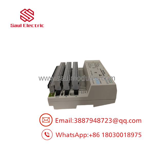
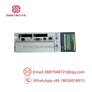
170BDI35600
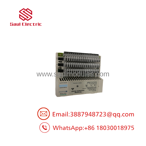
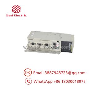
170BDI35600
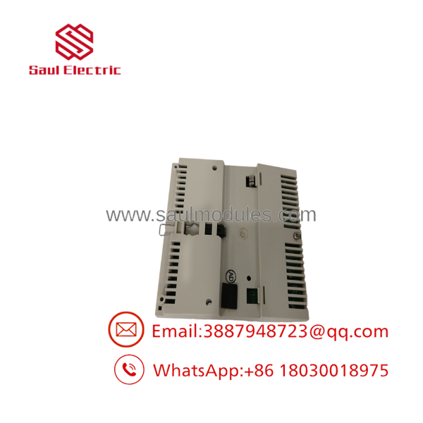
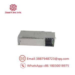
170BDI35600
Transparency SOP: QA & Testing
For New Surplus or refurbished 170BDI35600 inventory, a proper test should verify actual input switching.
- Confirm identification — Verify
170BDI35600on the physical label. - Inspect the module — Check housing condition, terminals, connector interfaces, LEDs, and labeling.
- Install on a compatible Momentum base — Confirm normal module recognition.
- Apply controlled 24 VDC signals — Use an isolated, protected test source.
- Test OFF state — Confirm the channel registers the expected inactive condition.
- Test ON state — Apply the appropriate DC signal and verify the channel transitions correctly.
- Exercise multiple channels — Repeat the test across the available inputs.
- Check indication — Confirm channel status indicators correspond with the applied signal.
- Verify controller data — Confirm the Momentum controller receives the expected input states.
- Record the result — Document channels tested, test voltage, hardware condition, and warranty classification.
A useful QA record should identify what was tested and how. “Tested OK” provides little information to a maintenance engineer buying a legacy spare.
The Veteran’s Tech Trap Guide
⚠️ Trap #1 — Check the field common before condemning the module.
A missing or loose 0 V reference can make multiple inputs appear faulty simultaneously. If several channels fail together, inspect the common/reference wiring first.
⚠️ Trap #2 — Don’t rely only on the input LED.
The LED tells you that the module sees a particular electrical condition. It does not automatically prove that the PLC application is interpreting the channel correctly.
PRO TIP: Compare the physical input state, module indication, and controller bit state. Those three observations quickly narrow the fault location.
⚠️ Trap #3 — Watch for inductive noise.
Inputs located near contactors, solenoids, motor starters, and long field cables can experience transient or noisy signals. If a channel flickers only when machinery starts or stops, investigate the field circuit before replacing the I/O module.
⚠️ Trap #4 — Don’t substitute based solely on “16 inputs, 24 VDC.”
The replacement must match the Momentum I/O architecture, input logic, common arrangement, wiring system, and application requirements. A similar-looking 16-point module may not be functionally equivalent.
Dynamic FAQ
Q: What is the Schneider 170BDI35600?
A: It is a Modicon Momentum 16-point 24 VDC discrete input module used to monitor binary field signals.
Q: How many inputs does the 170BDI35600 have?
A: It provides 16 discrete DC input channels.
Q: What devices can be connected to the 170BDI35600?
A: Typical applications include proximity sensors, photoelectric sensors, limit switches, pushbuttons, relay contacts, motor auxiliary contacts, valve feedback, and machine interlocks.
Q: What should I check if several inputs stop working at once?
A: Check the field 24 VDC supply, common/reference wiring, terminal connections, and module seating first. Multiple simultaneous failures often point toward a shared supply or common circuit rather than independent input-channel failures.
Q: Is the 170BDI35600 interchangeable with other Momentum digital input modules?
A: Not automatically. Verify the input voltage, logic, channel arrangement, terminal/base compatibility, and application configuration before selecting a substitute.
Q: How should New Surplus 170BDI35600 stock be verified?
A: Confirm the exact catalog number, inspect the housing and connector interfaces, install it on a compatible Momentum base, and apply controlled 24 VDC signals to verify the input channels. The supplier should clearly identify the unit as New Surplus, Used, or Refurbished and provide written warranty and return terms.

 Start Chat


