





Description
Product Introduction & Engineering Value
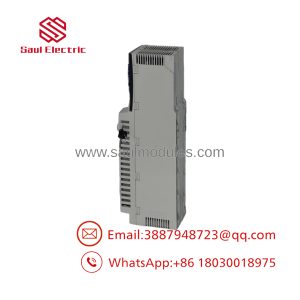
The TSXASY410 provides four independent analog output channels within the Premium I/O architecture. Depending on the selected configuration, channels can be used for standard industrial voltage or current control signals. That makes the module useful for applications ranging from drive-speed references to proportional valve commands.
The important point during replacement is that the output range and wiring configuration must match the existing application. A PLC program may contain scaling that assumes a particular raw-count range. Changing the electrical output configuration without checking the software can turn a correctly functioning replacement into an incorrect process command.
Technical Specifications
| Parameter | Specification |
|---|---|
| Catalog Number | TSXASY410 |
| Platform | Modicon Premium |
| Module Type | Analog output |
| Number of Outputs | 4 |
| Output Signal | Voltage / current |
| Typical Voltage Ranges | 0–10 V, ±10 V |
| Typical Current Ranges | 0–20 mA, 4–20 mA |
| Resolution | Up to 12-bit |
| Channel Configuration | Individually configurable according to supported range |
| Typical Loads | Drives, valves, actuators, analog controllers |
| Installation | Premium PLC rack |
| Programming Environment | PL7 / applicable Premium configuration software |
| Signal Scaling | Application-dependent |
| Isolation / Wiring | Verify against exact hardware revision and configuration |
Engineering caution: Legacy TSX documentation and reseller databases can contain conflicting descriptions of individual ASY-series modules. Before publishing a detailed electrical specification for procurement, verify the original Schneider hardware manual against the exact TSXASY410 revision.
Field Application & the “Trench” Experience
A Premium PLC controls a variable-speed pump through an analog speed reference. The pump normally receives a 4–20 mA command from one channel of the TSXASY410.
After a maintenance intervention, the pump immediately runs near maximum speed when the controller commands a low-speed condition.
The replacement module itself is functioning. The problem is configuration.
The original application expected one analog range while the replacement channel was configured differently. The PLC’s raw output value was being interpreted against the wrong electrical range, producing an incorrect physical command.
The maintenance team corrects the channel configuration, verifies the raw output, measures the actual current at the module terminals, and then confirms the pump response.
That is the correct sequence: PLC command → raw analog value → electrical output → field-device response.
Specific application scenarios:
- Variable-speed pump control: 4–20 mA or 0–10 V speed reference.
- Modulating control valves: proportional command signals for flow or pressure regulation.
- Damper control: analog position commands in HVAC and process ventilation systems.
- Process heating: analog control signals to power controllers or temperature-control equipment.
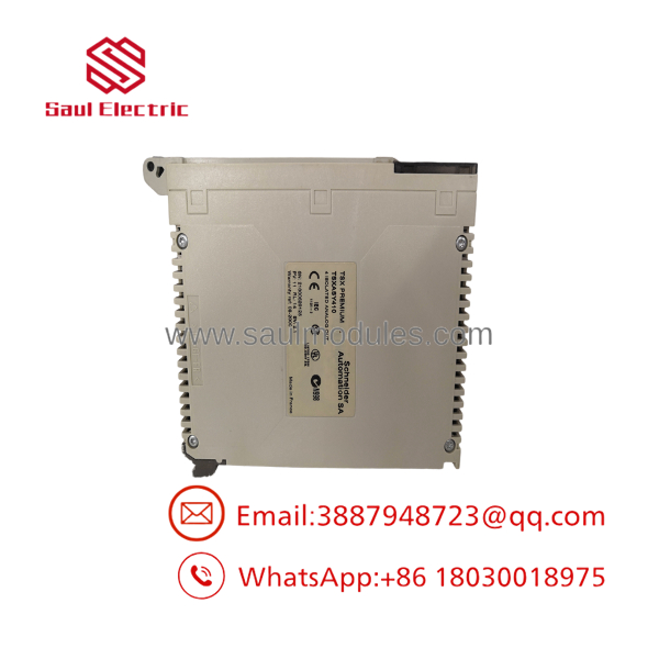
TSXASY410
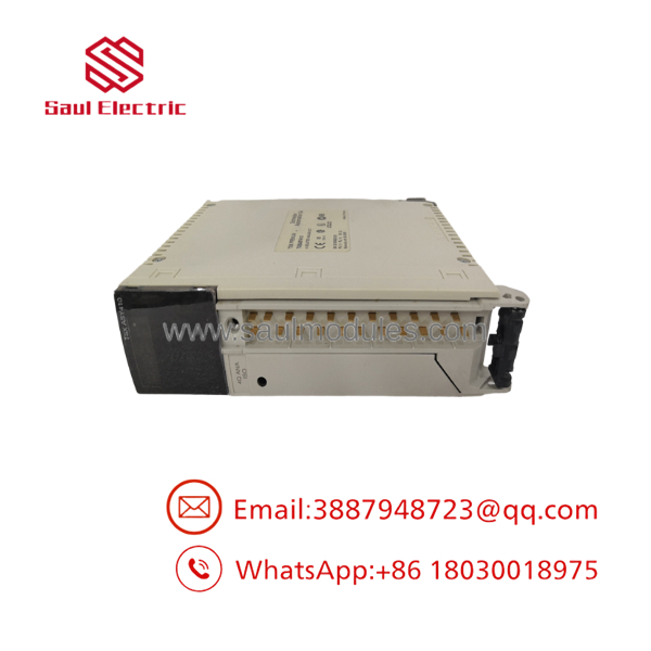
TSXASY410
Transparency SOP: QA & Testing
For New Surplus or refurbished TSXASY410 inventory, the output circuits should be tested using calibrated measurement equipment.
- Confirm identity — Verify
TSXASY410on the module label. - Inspect hardware — Check the housing, terminal/interface, connector, and labeling.
- Install on a compatible Premium rack — Confirm module recognition.
- Configure the test channel — Use a documented supported output range.
- Command a low-scale output — Measure the physical voltage/current at the terminals.
- Command a mid-scale output — Compare PLC raw value and measured output.
- Command the high-scale output — Confirm the output reaches the expected range without abnormal deviation.
- Repeat across channels — Exercise all four outputs where the test fixture permits.
- Verify polarity and scaling — Confirm the measured signal corresponds to the commanded value.
- Document results — Record the output range, measured values, hardware revision, and final stock condition.
Do not connect a tested analog output directly to a production actuator during initial verification. Use an appropriate load or measurement instrument first.
The Veteran’s Tech Trap Guide
⚠️ Trap #1 — Check the output range before connecting the actuator.
A 0–10 V command and a 4–20 mA command can represent the same engineering variable while requiring completely different field wiring and scaling.
PRO TIP: Measure the physical output with a calibrated meter before reconnecting a drive or valve.
⚠️ Trap #2 — Preserve the original scaling.
If the PLC application converts a raw output value into a speed, pressure, temperature, or valve position, document those scaling parameters before replacing the module.
⚠️ Trap #3 — Don’t assume all four channels are configured identically.
An existing machine may use different ranges on different channels. One channel could drive a VFD while another operates a proportional valve.
⚠️ Trap #4 — Protect the output from an incorrect load.
Analog output modules are signal-generation devices, not general-purpose power supplies. Verify the connected device’s input impedance and wiring requirements before commissioning.
Dynamic FAQ
Q: What is the Schneider ?
A: It is a four-channel analog output module for the Modicon Premium PLC platform, used to generate controlled voltage or current signals for field equipment.
Q: How many outputs does the provide?
A: It provides four analog output channels.
Q: What devices can be controlled with the ?
A: Typical applications include variable-frequency drives, proportional control valves, dampers, power controllers, and other equipment accepting standardized analog control signals.
Q: What should I check before replacing a ?
A: Verify the output range used by each channel, PLC scaling, terminal wiring, connected-device input requirements, Premium rack compatibility, and the original hardware revision.
Q: Can I connect a output directly to a VFD?
A: Potentially, if the VFD’s analog input specification matches the module’s configured output range and wiring requirements. Confirm the actual drive input specification before making the connection.
Q: How should New Surplus stock be tested?
A: Install it in a compatible Premium test rack, configure each applicable channel, command known output values, and measure the physical voltage/current with calibrated equipment. A supplier should clearly identify the unit as New Surplus, Used, or Refurbished and provide documented warranty and return terms.

 Start Chat


