





Description
Core Product Summary
The Sigmatek DDM163 (order code 05-008-163) is a digital conversion module — a combined digital input/output module — in Sigmatek’s DIAS modular automation system for PLC and machine-control applications. It combines eight digital outputs and eight digital inputs on one DIAS bus module, with all I/O processed automatically into the process image by the DIAS operating system.
The eight outputs are positive-switching (sourcing) +24 V / 2 A channels, protected against short circuit, with a permitted total of 6 A across all channels at 100% duty and a switching delay under 200 µs in each direction. The eight inputs read +24 V signals (signal “1” above +14 V, “0” below +8 V, typical switching threshold +11 V, 5 mA input current) with 5 ms input filters for noise suppression in harsh industrial environments. The module takes its logic supply (+5 V, typically 20 mA) from the DIAS bus, while field power is wired separately as +24 V/1 for the sensors (18–30 V DC) and +24 V/2 for the outputs. Connection is made through a DKL 013 terminal module with a 17-pole, three-row spring terminal strip, and yellow LEDs (outputs) and green LEDs (inputs) indicate signal status. The module is identified at the DIAS bus as 16#02 and, in hardware version 6.0, operates from 0 to +60 °C.
Key Technical Specifications
| Parameter | Value |
|---|---|
| Product type | Digital conversion (mixed) module, DIAS series |
| Article number | 05-008-163 (hardware version 6.0) |
| Digital outputs | 8, positive switching, +24 V / 2 A per channel, short-circuit protected |
| Total output current | Max 6 A across all 8 channels (100% duty cycle) |
| Output switching energy (inductive loads) | Max 0.65 J per channel; max 1.95 J per 4 channels |
| Output voltage drop (on) | ≤ 1 V |
| Output residual current (off) | ≤ 12 µA |
| Switch-on / switch-off delay | < 200 µs each |
| Output status indication | Yellow LEDs |
| Digital inputs | 8, +24 V typical (+30 V max) |
| Input signal levels | Low: < +8 V; High: > +14 V; typical threshold +11 V |
| Input current | 5 mA at +24 V typical |
| Input delay (filter) | 5 ms typical |
| Input status indication | Green LEDs |
| Field supply voltage | ‘+24 V/1 (sensors) and +24 V/2 (outputs), 18–30 V DC |
| DIAS bus supply | ‘+5 V, typically 20 mA, max 40 mA |
| Required terminal module | DKL 013 (05-024-013), 17-pole, 3-row spring terminal strip |
| DIAS bus module identification | 16#02 |
| Addressing | Automatic via process image; 16#00 READ BYTE inputs 1–8, 16#00 WRITE BYTE outputs 1–8 |
| Operating temperature | 0 to +60 °C |
| Storage temperature | −20 to +85 °C |
| Humidity | 0–95%, non-condensing |
| EMC immunity | EN 61000-6-2 (industrial environment) |
| Shock resistance | EN 60068-2-27, 150 m/s² |
| Standards note | UL (E247993) applies to earlier hardware versions; no UL at HW version 6.0 |
Detailed Product Overview
The DDM163 exists to solve a panel-density problem: rather than populating one input module and one output module, a single DIAS slot delivers eight sensor inputs and eight actuator outputs. For machines with grouped I/O — a small station with several proximity switches, limit switches or push-buttons on the input side and solenoid valves, contactors or indicator lamps on the output side — one module covers the complete station, reducing bus nodes, wiring runs and cabinet space.
The output side is engineered for direct actuator driving. Each of the eight channels sources up to 2 A continuously at +24 V, with short-circuit protection per channel. Two engineering constraints matter here. First, the 6 A group limit means a fully loaded module cannot run all eight channels at rated current simultaneously — the 24 V/2 supply and its cabling must be sized for the actual summed load, not for 8 × 2 A. Second, inductive loads: the outputs have internal suppression that limits inductive switching spikes (clamping groups of four outputs to −12.7 V against the supply), but Sigmatek still recommends a freewheeling diode directly at each inductive load such as a contactor coil, because the internal clamping diverts peak currents through the 0 V line — a long or thin 0 V feed can then cause unwanted reactions of outputs on the module. External voltage applied to an output must never exceed the supply voltage by more than 0.7 V.
The input side is deliberately slow and robust: a 5 ms filter (versus sub-microsecond output response) suppresses contact bounce and glitches from mechanical switches and 2-wire initiators, which is the correct trade-off for field sensing where microsecond response is irrelevant but noise immunity is not. Inputs accept both 2-wire initiators/limit switches and 3-wire sensors, powered from the separate +24 V/1 feed so that sensor load does not share the output supply.
Integration in the DIAS system is plug-in: the module identifies itself on the bus (code 16#02), the operating system maps the input byte and output byte into the process image, and no manual address configuration is required. Field wiring is made on the DKL 013 terminal module via spring terminals — inputs on terminals 1a–8a, outputs on 9a–16a, the two 24 V feeds on terminal 17, with row b distributing the supply voltages and row c commoned to GND. One documented operating characteristic: outputs may be disabled by switching off the +24 V supply; the yellow output LEDs then show the real electrical output state, not the CPU command, which is useful during commissioning but must be understood when interpreting LED indications.
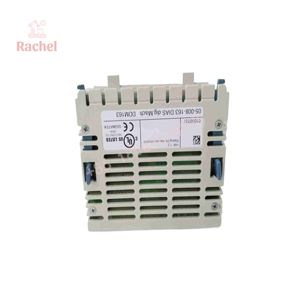
DDM163
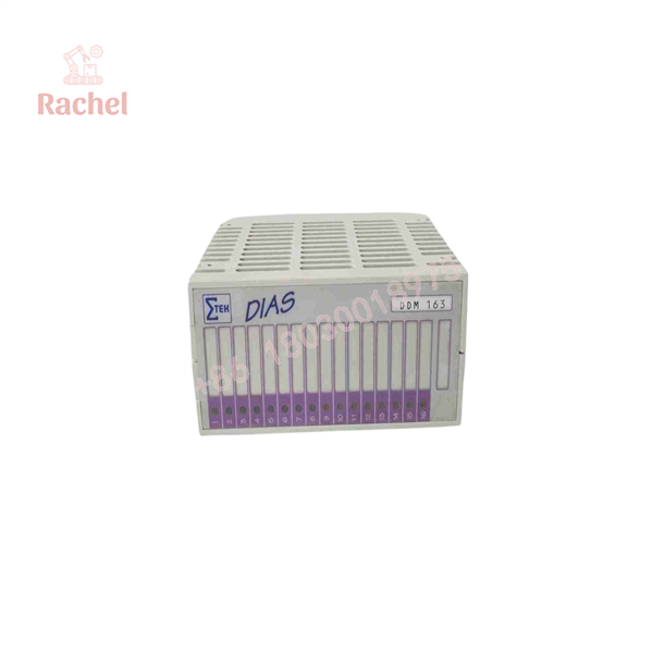
DDM163
Engineering Selection Highlights
- 8 DI + 8 DO in one DIAS slot — halves module count for balanced I/O stations; confirm the 6 A group budget covers the summed continuous output load, since 8 × 2 A exceeds it.
- 2 A positive-switching, short-circuit-protected outputs — drives solenoid valves and contactor coils directly without interposing relays, provided the inductive switching energy stays within 0.65 J per channel.
- Separate +24 V/1 (sensor) and +24 V/2 (output) supplies, 18–30 V DC — isolating field sensor power from actuator power prevents output switching noise from disturbing inputs; both feeds plus GND land on terminal 17 of the DKL 013.
- 5 ms input filters with defined thresholds (<8 V low, >14 V high) — safe for 2-wire initiators and mechanical limit switches in electrically noisy cabinets; not suitable where sub-millisecond input response is required.
- DKL 013 terminal module is a required companion — the DDM163 has no field terminals of its own; the order must include the DKL 013 (05-024-013) with its 17-pole spring terminal strip, and its GND contact springs must be bonded to the cabinet earth via the mounting rail.
- Automatic DIAS process-image addressing (ID 16#02) — inputs and outputs appear as one READ byte and one WRITE byte at address 16#00, so no DIP-switch or software address setup is needed.
- UL status depends on hardware version — the UL listing (E247993) applies to earlier hardware versions and explicitly not to HW version 6.0; verify the hardware version marking when UL marking of the installed system is required.
Dimensions, Mounting & Connection Notes
- Mechanical dimensions per the datasheet drawing: 93 mm × 98 mm module front with 45 mm depth (80 mm mounting dimension shown in the figure); the module mounts on a top-hat rail as part of a DIAS assembly.
- All field wiring lands on the DKL 013 terminal module’s 17-pole, three-row spring terminal strip: row a carries signals (inputs 1–8, outputs 1–8), row b distributes +24 V/1 to the input group and +24 V/2 to the output group, row c is GND throughout.
- Power feeds connect at terminal 17: +24 V/1 at 17a, +24 V/2 at 17b, GND at 17c.
- Size the +24 V and 0 V supply conductors for the maximum current drawn from the group; an undersized or over-long 0 V lead can cause unwanted output reactions when inductive loads switch.
- Do not apply an external voltage to any output that exceeds the module supply voltage by more than 0.7 V.
- Inductive loads (contactor coils, valve solenoids) should carry a freewheeling diode or RC suppressor directly at the load, even though the outputs have internal clamping.
- The DKL 013’s GND spring contacts must be connected to cabinet earth through the mounting rail, and the GND terminal routed to a common earthing bus bar with the shortest possible conductors.
- Avoid running input lines parallel to load-current circuits; separate signal and power routing is a stated installation requirement.
System Compatibility & Integration Requirements
| Item / Dependency | Verified Compatibility or Requirement | Practical Note |
|---|---|---|
| System family | Sigmatek DIAS modular automation system | Module identification at the bus: 16#02; I/O processed automatically into the process image |
| Field terminal connection | DKL 013 terminal module (05-024-013) | 17-pole, 3-row spring terminal strip; inputs 1a–8a, outputs 9a–16a, feeds at terminal 17 |
| Sensor supply | ‘+24 V/1, 18–30 V DC | Consumption equals the connected initiators’ current draw |
| Output supply | ‘+24 V/2, 18–30 V DC | Consumption equals output load, max 6 A total |
| Logic supply | ‘+5 V from the DIAS bus | Typically 20 mA, max 40 mA — no external 5 V wiring |
| Sensor types | 2-wire initiators, mechanical limit switches, 3-wire initiators | Wiring diagrams per datasheet; threshold +11 V typical |
| Output loads | Resistive and inductive up to 2 A/channel | Inductive loads limited to 0.65 J/channel internally; freewheeling diode at the load recommended |
| Addressing | 16#00 READ BYTE (inputs 1–8), 16#00 WRITE BYTE (outputs 1–8) | Handled automatically by the DIAS operating system |
| Grounding | DKL 013 GND terminal 17c to a common earthing bus bar; DKL GND contact springs to cabinet earth via top-hat rail | Keep ground connections as short as possible |
| EMC / environment | EN 61000-6-2 immunity; 0–60 °C operation, 0–95% RH non-condensing | Suitable for industrial-area installations |
FAQ
What is the Sigmatek DDM163?
It is a DIAS digital conversion module (order code 05-008-163) combining eight +24 V digital inputs and eight +24 V / 2 A positive-switching, short-circuit-protected digital outputs in a single Sigmatek DIAS bus module.
What does the DDM163 do?
It reads eight field sensor signals into the DIAS process image and switches eight actuator channels from it, with automatic addressing by the DIAS operating system (module ID 16#02) and LED status indication for every channel.
What are its key electrical specifications?
Outputs: 2 A per channel, 6 A total at 100% duty, ≤1 V voltage drop, <200 µs switching delay, 0.65 J inductive switching energy per channel. Inputs: +24 V typical, “1” above +14 V, “0” below +8 V, 5 mA input current, 5 ms input filter. Field supply: 18–30 V DC on two separate feeds; +5 V logic comes from the DIAS bus (typically 20 mA).
Which terminal module does it require?
The DKL 013 (article 05-024-013) with its 17-pole, three-row spring terminal strip; the DDM163 itself carries no field terminals, and the two modules mount together on the DIAS rail.
Which sensors can connect to the inputs?
Two-wire initiators, mechanical limit switches, and three-wire initiators (e.g., 3-wire proximity sensors), powered from the dedicated +24 V/1 feed.
How should inductive loads be wired?
Directly at up to 2 A per channel, with a freewheeling diode (or RC network) at the load recommended by Sigmatek; the outputs’ internal protection clamps groups of four outputs, but external suppression avoids voltage spikes disturbing other circuits.
What environmental limits apply?
Operating temperature 0 to +60 °C, storage −20 to +85 °C, humidity 0–95% non-condensing, shock resistance 150 m/s² per EN 60068-2-27, EMC immunity per EN 61000-6-2 for industrial areas.
Does the DDM163 have UL approval?
Earlier hardware versions carry UL recognition (E247993); hardware version 6.0 does not, per the datasheet — check the hardware version marking when a UL-marked installation is required.
Verification & Troubleshooting Notes
- LED diagnosis: green LEDs mirror the eight inputs and yellow LEDs the eight outputs, giving an immediate electrical comparison against the CPU command; during commissioning, compare LEDs against the process-image bytes (READ 16#00, WRITE 16#00) to isolate wiring from logic faults.
- Outputs show “on” but CPU says “off” (or vice versa): if the +24 V/2 supply has been switched off, the yellow LEDs show the true electrical output state rather than the CPU output — check whether output disable via supply switching is part of the machine’s operating mode before diagnosing the module.
- Outputs switching unexpectedly when inductive loads operate: the internal suppression routes switching spikes into the 0 V line; verify the 0 V conductor cross-section and length against the group load, and confirm freewheeling diodes/RC suppressors are fitted at all inductive loads.
- Inputs unstable or noisy: the 5 ms filters handle most glitches, but input lines must not be run parallel to load circuits — reroute signal wiring and check that 2-wire initiators’ residual current does not hold an input above the +8 V low-level limit.
- Short-circuit on an output: outputs are short-circuit protected and will not be destroyed, but the affected channel will not function until the fault is located and cleared; use the yellow LEDs and channel-by-channel load disconnection to identify the branch.
- Module not recognized / no communication: confirm the module sits correctly on the DIAS bus connectors and that the +5 V bus supply is present (typically 20 mA draw); addressing is automatic, so a missing module appears in the system configuration rather than as an address conflict.
- Grounding-related faults: the DKL 013 GND terminal and its mounting-rail contact springs must both be bonded to cabinet earth; floating or long ground connections are a documented cause of disturbed module behavior.
- All diagnostics should be performed with the wiring de-energized where possible; the module is a wiring-density component and module-internal faults are not field-repairable.

 Start Chat


