





Description
Core Product Summary (Brand / Model / Key Attributes)
The SMC EX120-SPR1-B is a PROFIBUS-DP serial interface (SI) unit designed for direct mounting on SMC VQ and SV series solenoid valve manifolds. It functions as a compact fieldbus slave that enables control of up to 16 single-solenoid or 8 double-solenoid valves (maximum 16 coils) via the PROFIBUS-DP protocol.
This EX120-series unit provides 16 output points with Minus Common polarity, supports automatic baud-rate detection from 9.6 kbit/s to 12 Mbit/s, and uses a 9-pole D-Sub connector for the bus and a 5-pole round connector for power. Separate 24 V DC supplies feed the electronics (max. 70 mA) and valve load (max. 1.4 A). The unit carries CE marking and an IP20 enclosure rating.
Key Technical Specifications
| Parameter | Specification |
|---|---|
| Product type | PROFIBUS-DP SI unit (serial interface) |
| Housing / mounting | EX120: direct mount (no ribbon cable, no DIN rail) |
| Compatible valves | VQ1000/2000, SV series (Negative/Minus Common) |
| Number of outputs | 16 points (max. 16 coils) |
| Output polarity | Minus Common |
| Max. power per output | 2.1 W |
| Protocol | PROFIBUS-DP (IEC 61158 / EN 50170) |
| Baud rate | 9.6 kbit/s – 12 Mbit/s (automatic detection) |
| Power supply | 24 V DC ±10 % (21.6–26.4 V DC); separate electronics & valve supplies |
| Electronics current | Max. 70 mA (no load) |
| Valve load current | Max. 1.4 A |
| Bus connector | 9-pole D-Sub |
| Power connector | 5-pole round (DIN 45322) |
| Enclosure | IP20 |
| Operating temperature | 0 °C to +50 °C |
| Storage temperature | –20 °C to +85 °C |
| Relative humidity | 10–95 % (no condensation) |
| Approvals | CE marking |
Detailed Product Overview
The SMC EX120-SPR1-B serves as the fieldbus gateway between a PROFIBUS-DP master and an SMC pneumatic valve manifold. It converts cyclical PROFIBUS-DP output data into individual 24 V DC drive signals for the connected solenoid valves, eliminating the need for discrete wiring of each coil.
The EX120 housing is intended for direct mounting on the valve manifold without an intermediate ribbon cable, making it suitable for compact VQ and SV series installations. The internal electronics are common across the EX120/EX121/EX122 family; only the mechanical interface differs. Because the unit has no discrete input channels, it is used exclusively for output control of valves.
Power is supplied through a single 5-pole round connector that feeds both the SI electronics and the valve load circuits. The two supplies share a common reference but are otherwise isolated, allowing independent sizing of the valve power source. Each output is rated for a maximum of 2.1 W and is protected by micro-fuses arranged one per byte.
Station address can be set either by two front-panel rotary switches (hardware mode, addresses 02–99) or via the PROFIBUS protocol (software mode, addresses 02–126). A internal sliding switch selects the addressing method and determines which GSD file must be used for configuration. Automatic baud-rate detection simplifies commissioning on networks running at any standard PROFIBUS-DP speed up to 12 Mbit/s.
Diagnostic LEDs on the front face indicate power status (RUN), bus fault (BF) and general diagnosis (DIA), including conditions such as low valve supply voltage. The unit is designed for industrial environments with an IP20 rating and an operating temperature range of 0 °C to +50 °C.
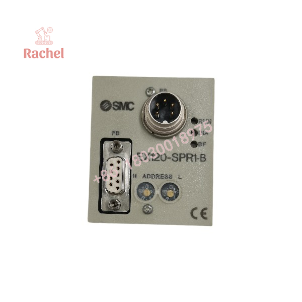
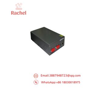
EX120-SPR1-B
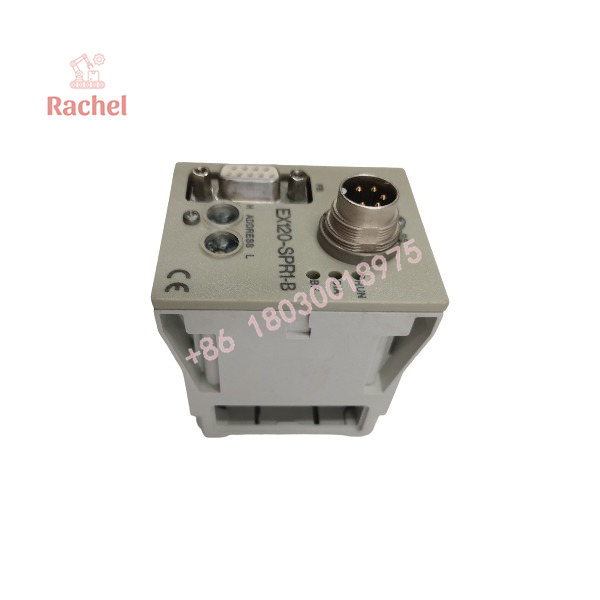
EX120-SPR1-B
Engineering Selection Highlights
- Direct-mount EX120 housing matches VQ1000/2000 and SV series manifolds that require no ribbon-cable interface.
- Maximum of 16 output coils determines the largest single-solenoid or double-solenoid valve combination that can be controlled by one unit.
- Minus Common output polarity requires corresponding Negative Common valve configurations (e.g., VQ…N).
- Separate electronics and valve power supplies allow independent current budgeting; electronics draw ≤70 mA while valves may draw up to 1.4 A.
- Hardware address switches (default 03) provide visible station numbering and must be paired with the matching GSD file (SMCB1401).
- IP20 protection and 0–50 °C operating range define the environmental limits for panel or machine mounting.
- Automatic baud-rate detection and support for all standard PROFIBUS-DP speeds up to 12 Mbit/s simplify network integration.
Dimensions, Mounting & Connection Notes
The EX120 housing is designed for direct plug-in mounting onto the corresponding valve manifold; no DIN-rail adapter or ribbon-cable interface is used. Bus connection is made via a standard 9-pole D-Sub socket. Power is supplied through a 5-pole round connector conforming to DIN 45322. The unit occupies the manifold’s SI-unit position and requires the manifold sub-base to be ordered with the appropriate PROFIBUS-compatible interface designation.
System Compatibility & Integration Requirements
| Item / Dependency | Verified Compatibility or Requirement | Practical Note |
|---|---|---|
| Valve series | VQ1000/2000, SV (Negative/Minus Common) | Direct mounting only; EX121/EX122 variants required for SY series |
| Protocol | PROFIBUS-DP slave | Compatible with any certified PROFIBUS-DP master |
| Address setting | Hardware (rotary switches 02–99) or software (02–126) | Sliding switch selects mode; correct GSD file required |
| Bus connection | 9-pole D-Sub | Shielded twisted-pair cable per EN 50170 |
| Power connection | 5-pole round connector (DIN 45322) | Separate +24 V feeds for electronics and valves |
| Configuration file | SMCB1401.GSD (HW) / SMCB1400.GSD (SW) | Must match address-setting mode |
FAQ
What is the SMC -SPR1-B?
It is a PROFIBUS-DP serial interface unit that controls up to 16 solenoid-valve coils on SMC VQ or SV series manifolds.
Which valve series can be used with the EX120-SPR1-B?
VQ1000/2000 and SV series valves configured for Negative/Minus Common polarity.
How many valves can one unit control?
A maximum of 16 single-solenoid valves or 8 double-solenoid valves (total of 16 coils).
What power supply is required?
24 V DC ±10 % (21.6–26.4 V). Separate supplies are used for the electronics (≤70 mA) and the valve load (≤1.4 A).
How is the PROFIBUS station address set?
By two front-panel rotary switches (hardware mode, 02–99) or via the bus protocol (software mode, 02–126). An internal sliding switch selects the mode.
What connectors are used?
9-pole D-Sub for the PROFIBUS bus and a 5-pole round connector for power.
Does the unit have digital inputs?
No. The EX120-SPR1-B is an output-only SI unit.
Verification & Troubleshooting Notes
Front-panel LEDs provide the primary diagnostic information:
- Green RUN LED indicates electronics power is present.
- Red BF LED signals a bus fault (no communication with the master).
- Red DIA LED indicates a diagnostic condition such as low valve supply voltage.
Confirm that the correct GSD file matching the address-setting mode is loaded in the PROFIBUS master. Verify that the rotary-switch address (if used) is unique on the network and that both power supplies are within the 21.6–26.4 V range. Ensure bus termination resistors are fitted at both ends of the PROFIBUS segment and that cable lengths comply with the baud-rate limits given in the PROFIBUS-DP standard.

 Start Chat


