





Description
Product Introduction & Engineering Value
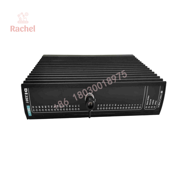
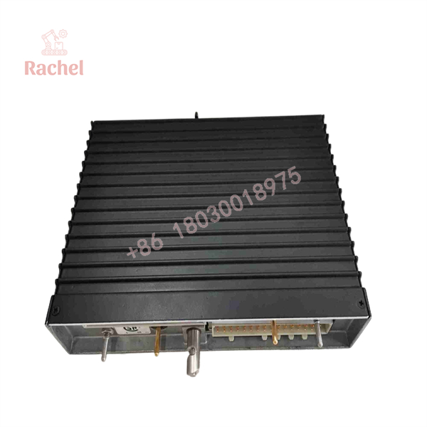
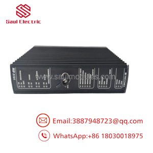
The Triconex 3301 is the 32-channel digital-input module used in the Trident safety controller architecture. It accepts 24 VDC discrete field signals such as switches, contacts, permissives, and status indications. Three independent processing channels scan the input data, with the resulting information transmitted to the Trident main processors for voting and application processing.
The module incorporates continuous diagnostics, including Force-to-Value Diagnostic (FVD), and is mechanically keyed for correct baseplate installation. For legacy Trident systems, the 3301 is therefore a system-specific safety I/O component rather than a generic 24 VDC PLC input card.
Technical Specifications
| Specification | Triconex 3301 |
|---|---|
| Product family | Trident |
| Module designation | Digital Input Module |
| Model | 3301 |
| Number of points | 32 |
| Input arrangement | Commoned |
| Nominal input voltage | 24 VDC |
| Operational voltage range | 15–30 VDC |
| Absolute maximum input voltage | 33 VDC |
| Absolute maximum reverse voltage | −0.6 VDC |
| Input delay | <10 ms |
| Time constant | 6.4 ms, −3 dB at 25 Hz |
| Input impedance without baseplate | >30 kΩ |
| Input impedance with baseplate | Approximately 3 kΩ |
| Input power | 0.2 W/point at 24 VDC |
| Input power at 33 VDC | 0.5 W/point |
| OFF region | 0–5 VDC |
| Transition region | 6–14 VDC |
| ON region | 15–30 VDC |
| Diagnostic method | Force-to-Value Diagnostic (FVD) |
| FVD test time | <2 ms/test |
| Maximum toggle rate for diagnostic coverage | <20/sec |
| ADC scan time | <1 ms for all 32 points |
| Functional-to-protective-earth isolation | 500 VDC minimum |
| Functional-to-functional/logic isolation | 800 VDC minimum |
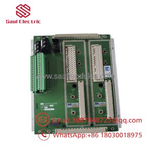
| Associated baseplate | 2301 Digital Input Baseplate |
These values are taken from the Trident Planning and Installation Guide’s model-specific 3301 specification table.
Input Thresholds
The input thresholds deserve attention during commissioning:
- 0–5 VDC: OFF region
- 6–14 VDC: transition region
- 15–30 VDC: ON region
A field signal sitting continuously in the 6–14 VDC transition region should not be treated as a valid logic state.
3301
3301
Diagnostic Architecture
The 3301 uses three independent processing channels. Each channel scans the input points and prepares its own input data for transmission to the main processors. The Trident MPs then vote the input information before the control application uses it.
The module also continuously performs diagnostics. A detected channel problem activates the module’s fault indication and system alarm. The documentation describes the DI module as capable of continuing proper operation in the presence of a single fault and, under certain conditions, multiple faults.
Force-to-Value Diagnostic
FVD is particularly relevant when troubleshooting field wiring.
The documented diagnostic test time is less than 2 ms per test, while the specified ADC scan time is less than 1 ms for all 32 points. The diagnostic architecture is intended to detect loss of input visibility rather than merely determine whether a channel happens to be high or low.
Field Application & “Trench” Experience
A typical 3301 installation may monitor:
- Emergency shutdown contacts
- Valve-position switches
- Motor permissives
- Pressure-switch contacts
- Level-switch status
- Pump or compressor running feedback
- Equipment interlocks
- Process permissive signals
Consider a legacy process unit where several shutdown permissives are wired to a Trident 3301. If one field contact begins producing an intermittent 8–10 VDC signal, the problem cannot be treated as a simple PLC logic issue. The voltage is inside the documented transition region, so the field circuit, contact resistance, termination, and associated power supply should all be investigated.
Niche Applications
Safety shutdown status monitoring
The 3301 can acquire discrete field conditions used by the Trident application for permissive and shutdown logic.
Process interlock monitoring
Commoned 24 VDC inputs are suitable for monitoring equipment interlocks and discrete process conditions.
Legacy Trident replacement inventory
Because the 3301 is tied to the Trident I/O architecture, maintaining a tested spare can reduce the impact of an unexpected I/O failure.
Transparency SOP: QA & Testing
For a New Surplus, Refurbished, or Working Surplus 3301, a powered-up LED check is not enough.
Recommended Incoming Inspection
- Verify the exact model — Confirm the nameplate reads
3301. - Inspect the module keying — Ensure the mechanical keying has not been damaged or modified.
- Inspect the connector — Check for bent contacts, contamination, corrosion, or mechanical damage.
- Verify channel indicators — Test the expected PASS, FAULT, ACTIVE, and field-input indications.
- Apply qualified 24 VDC signals — Exercise representative input channels across the valid operating range.
- Verify threshold behavior — Confirm OFF, transition, and ON regions.
- Test all 32 channels — A complete acceptance test should not rely on a sample of only a few inputs.
- Test diagnostics — Verify applicable FVD and fault-detection behavior using an approved test procedure.
- Check scan behavior — Confirm correct reporting of input changes.
- System integration test — Verify communication with the Trident MPs and the configured control application.
The published specification requires particular attention to the 15–30 VDC ON range and the diagnostic limits.
Veteran’s Tech Trap Guide
Trap 1 — Confusing 3301 with 2301
This is the most common identification error.
3301 = Digital Input Module
2301 = Digital Input Baseplate
The Trident documentation lists them as separate components of the digital-input assembly.
PRO TIP: When ordering a replacement, verify whether the failed item is the electronic DI module or the field-termination/baseplate assembly.
Trap 2 — Assuming any 24 VDC digital-input card can substitute
The 3301 is not simply a 32-channel PLC input module. It is designed around the Trident architecture, including independent processing channels, diagnostics, mechanical keying, and communication with the Trident MPs.
A generic PLC DI card cannot reproduce that architecture.
Trap 3 — Ignoring the transition voltage
A field signal between 6 and 14 VDC falls within the documented transition region.
PRO TIP: If a channel appears intermittent, measure the actual terminal voltage under operating conditions rather than checking only the PLC/Trident logic state.
Trap 4 — Treating 32 channels as 32 isolated inputs
The 3301 is specified as 32 commoned points. The field wiring arrangement therefore needs to match the applicable Trident baseplate and field-power architecture.
Dynamic FAQ
What is Triconex 3301?
The Triconex 3301 is a 32-point, 24 VDC commoned Digital Input Module for the Trident safety controller system.
How many inputs does the 3301 provide?
It provides 32 digital input points. The inputs are commoned rather than individually isolated.
What voltage does the 3301 accept?
The nominal input voltage is 24 VDC, with an operational range of 15–30 VDC and an absolute maximum input voltage of 33 VDC.
What is the associated Triconex baseplate?
The standard digital-input architecture uses the 2301 Digital Input Baseplate. The 2301 and 3301 perform different functions and should be ordered separately when required.
Is the 3301 a TMR input module?
The 3301 belongs to the Trident redundant safety-controller architecture, where three independent processing channels handle the module’s input data and the main processors vote the resulting data. It should not be confused with unrelated reseller descriptions that classify it as an ordinary simplex PLC input card.
What should I verify when purchasing New Surplus 3301?
Confirm the exact 3301 model, hardware revision, physical condition, connector/keying condition, 32-channel operation, diagnostic performance, Trident compatibility, and functional-test evidence. For safety-system spare inventory, document the supplier’s warranty separately from any original OEM warranty.
Procurement identification:
Triconex 3301 — Trident 32-Point 24 VDC Digital Input Module
Do not confuse:
3301 = DI Module
2301 = DI Baseplate
3201 = Communication Module

 Start Chat


