





Description
Product Introduction & Engineering Value
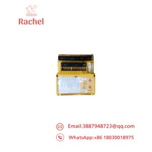
This particular IPC704 configuration is built around a relatively high-bandwidth vibration measurement path: the input is specified at 10 pC/g, the output at 20 µA/g, with a 2 Hz high-pass filter and 10 kHz low-pass filter. That makes the unit suitable for transferring conditioned dynamic signals from piezoelectric accelerometers into downstream monitoring or control equipment.
The A2 configuration is the detail engineers should not overlook. It identifies the explosive-environment version using intrinsic-safety protection. The IPC704 converts a charge-based sensor signal into a current or voltage signal, with the electronics housed in a molded aluminum enclosure.
Technical Specifications
| Parameter | Specification |
|---|---|
| Manufacturer | Vibro-Meter |
| Model | IPC 704 |
| Part Number | 244-704-000-042-A2-B01-C10-D20-E2-F10000-C0-H0-I0 |
| Primary Function | Charge amplifier / signal conditioner |
| Sensor Type | Piezoelectric transducer |
| Environment | A2 — Explosive, Ex i |
| Transfer Unit | pC/g → µA/g |
| Input Sensitivity | 10 pC/g |
| Output Sensitivity | 20 µA/g |
| High-Pass Filter | 2 Hz |
| Low-Pass Filter | 10,000 Hz |
| Installation Code | G0 / C0 — signal conditioner without industrial housing |
| Input Cable Fitting | H0 |
| Output Cable Fitting | I0 |
| Supply Voltage | 18–30 VDC |
| Maximum Current Consumption | 25 mA |
| Operating Temperature | −30 to +85°C |
| Storage Temperature | −40 to +85°C |
| Humidity | Up to 95% RH, non-condensing |
| Protection Rating | IP40 |
The IPC704 supports either 2-wire current transmission or 3-wire voltage transmission depending on the configured version. For 2-wire current transmission, published specifications identify a 12 mA ±0.5 mA standing current and a maximum dynamic signal of ±5 mA peak. The 3-wire configuration provides a 7.5 V ±0.2 V standing voltage with up to ±5 V peak dynamic signal.
What the Ordering Code Tells You
A2 — Environment: Ex i / explosive atmosphere configuration.
B01 — Transfer unit: pC/g to µA/g.
C10 — Input sensitivity: 10.00 pC/g.
D20 — Output sensitivity: 20.00 µA/g.
E2 — High-pass filter: 2 Hz.
F10000 — Low-pass filter: 10,000 Hz.
G0/C0 — Installation: Signal conditioner only, without industrial housing.
H0 — Input cable fitting: No fitting/hole specified.
I0 — Output cable fitting: No fitting/hole specified.
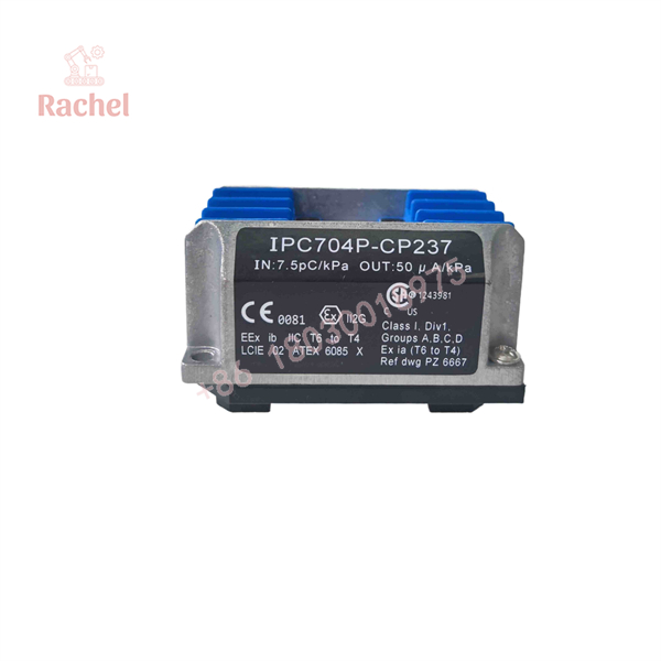
244-704-000-042-A2-B01-C10-D20-E2-F10000-C0-H0-I0
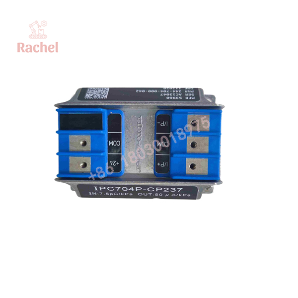
244-704-000-042-A2-B01-C10-D20-E2-F10000-C0-H0-I0
Field Application & the “Trench” Experience
A realistic failure occurs on a compressor train where an accelerometer is still producing a valid charge signal, but the control-room vibration indication has become unstable. Replacing the accelerometer does nothing. The actual problem is the charge-conditioning stage between the sensor and the monitoring system.
This is where an IPC704 such as 244-704-000-042-A2-B01-C10-D20-E2-F10000-C0-H0-I0 becomes important. The replacement must match the sensor’s charge sensitivity and the receiving system’s expected signal scaling. Installing an IPC704 with the wrong C/D configuration can produce a perfectly healthy-looking output that represents the wrong vibration level.
Niche application scenarios
- Centrifugal compressor bearing monitoring
Conditioning piezoelectric accelerometer signals before transmission to machinery-monitoring electronics. - Gas turbine auxiliary equipment
Filtering low-frequency mechanical movement while retaining vibration information through the 10 kHz upper cutoff. - Reciprocating compressor vibration measurement
Processing dynamic acceleration signals where the sensor provides a charge output rather than a directly standardized process signal. - Dynamic pressure pulsation measurement
The IPC704 architecture can also be used with compatible piezoelectric dynamic-pressure sensors.
Transparency SOP: QA & Testing
For New Surplus or Refurbished stock, the correct test is not merely “power applied, LED on.” This device is part of a measurement chain.
Inspection: Confirm the complete ordering code, enclosure condition, terminals, connector interfaces, and identification markings.
Electrical test: Apply an appropriate 18–30 VDC supply and verify current consumption and output behavior.
Signal test: Use a calibrated charge source or compatible piezoelectric test signal to verify the 10 pC/g input and 20 µA/g output relationship.
Filter test: Confirm the expected high-pass behavior around 2 Hz and low-pass behavior around 10 kHz.
Transmission test: Verify the configured current or voltage output under representative dynamic input conditions.
Final QA: Record the exact part number and test results. For an Ex i unit, documentation of the actual configuration matters as much as the basic functional test.
The Veteran’s Tech Trap Guide
⚠️ Trap #1 — Matching only “IPC704.”
That is not enough. The IPC704 is an order-configured product. C10/D20/E2/F10000 define important measurement characteristics. A different IPC704 can look physically similar while having a different sensitivity or filter configuration.
⚠️ Trap #2 — Confusing charge sensitivity with voltage sensitivity.
This configuration is specified in pC/g at the input and µA/g at the output. Do not substitute an accelerometer or conditioner based solely on its physical connector. The electrical transfer relationship has to match.
⚠️ Trap #3 — Ignoring the Ex i designation.
The A2 code is not an optional marketing label. It identifies the explosive-environment version. If the original installation is part of a hazardous-area measurement loop, replacing it with a standard IPC704 configuration can create a certification and system-approval problem.
PRO TIP: Before ordering a replacement, record the entire part number rather than just 244-704-000-042. For this product family, the suffix is effectively the configuration specification.
Dynamic FAQ
What is 244-704-000-042-A2-B01-C10-D20-E2-F10000-C0-H0-I0?
It is a Vibro-Meter IPC704 signal conditioner / charge amplifier-integrator configured for piezoelectric transducers. The documented configuration uses a 10 pC/g input sensitivity, 20 µA/g output sensitivity, 2 Hz high-pass filtering, and 10 kHz low-pass filtering.
Is this an accelerometer?
No. The IPC704 is the signal-conditioning electronics used with a compatible piezoelectric sensor. It receives the sensor’s charge signal and converts it into a current or voltage signal suitable for downstream monitoring equipment.
What does A2 mean?
A2 identifies the explosive / Ex i configuration in the IPC704 ordering system. This must be matched to the hazardous-area design and associated certification requirements.
What does C10-D20 mean?
For this ordering configuration, C10 specifies a 10.00 pC/g input sensitivity, while D20 specifies a 20.00 µA/g output sensitivity. These values establish the signal-conditioning relationship and should be matched to the existing measurement system.
What are E2 and F10000?
E2 specifies a 2 Hz high-pass filter, while specifies a 10,000 Hz low-pass filter. Together they define the configured frequency passband of the signal-conditioning stage.
Can this IPC704 be used with any Vibro-Meter accelerometer?
No. Sensor sensitivity, signal type, hazardous-area requirements, and the IPC704 ordering configuration must all be compatible. The IPC704 is intended for compatible piezoelectric transducers rather than being a universal accelerometer interface.
Is New Surplus the same as factory-new OEM stock?
No. New Surplus normally means unused inventory that has entered the secondary market. For a safety-related vibration-monitoring application, request photographs of the actual unit, the complete part number, serial/identification information, condition statement, and available functional-test records.
What warranty should be required?
For industrial instrumentation, the warranty should be stated explicitly on the quotation. A seller’s warranty is separate from an OEM factory warranty. For an Ex i measurement device, also request confirmation that the supplied configuration corresponds to the required hazardous-area application.

 Start Chat


