





Description
Product Introduction & Engineering Value
Chasing engine hunt on a generator set at startup is a massive time-sink, usually caused by sluggish actuator response or poor gain tuning on an old analog speed control box. The Woodward 8290-191 handles this issue directly by providing a dedicated, fast-acting analog control loop designed specifically to mate with Woodward’s Electrically Powered Actuator series. Because it relies on a high-velocity inner current loop, it translates raw magnetic pickup frequency changes into physical throttle adjustments without the processing delays found in larger, multi-purpose control units.
Field engineers rely on this EPG controller because it strips away unnecessary software complexity. It provides an immediate, hardware-level response to transient load steps, which is exactly what you need when stabilizing smaller diesel or gaseous-fueled engines running in standalone or prime power configurations. When you drop this module into a standard 24V control panel, you get a predictable speed loop that does not require proprietary software to calibrate or maintain.
Technical Specifications
- Input Power: 18–32 Vdc (24 Vdc nominal), reverse-polarity protected
- Actuator Compatibility: Designed to drive standard EPG 512 or 1712 style actuators
- Speed Input Signal: Accepts 1 to 30 Vrms from a standard Magnetic Pickup Unit (MPU)
- Frequency Range: Capable of tracking engine speed pulses up to 3000 Hz
- Steady-State Regulation: Isochronous operation within ±0.25% of rated speed
- Adjustments: Onboard multi-turn potentiometers for Rated Speed, Gain, and Reset (Stability)
- Auxiliary Input: Includes dedicated terminals for remote speed trim adjustments (potentiometer or analog bias)
- Ambient Temperature: Rated for operation from -40°C to +75°C inside localized enclosures
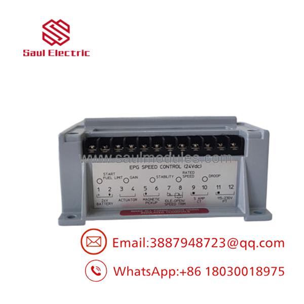
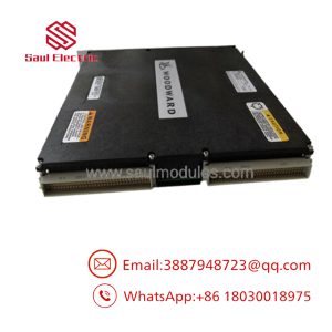
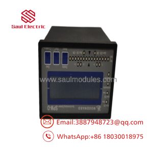
- 8290-191
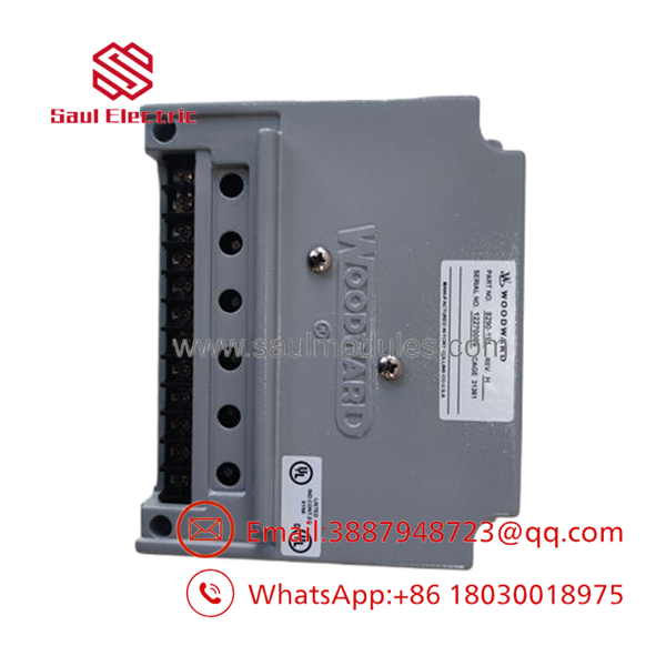
- 8290-191
Field Application & The “Trench” Experience
The Hunting Standby Generator
We were called out to an emergency backup generator site at a municipal water treatment facility where an older inline-6 diesel engine was surging violently upon start, preventing the automatic transfer switch from locking in. The onsite maintenance team had already swapped out the fuel filters and inspected the mechanical linkage. When we checked the actuator drive lines, we found that the internal power transistors on their original speed control box were failing under load, sending chopped voltage to the actuator. We mounted a new surplus 8290-191 module onto the bulkhead, terminated the 24V supply and MPU lines, and adjusted the multi-turn potentiometers. The engine settled into a smooth, rock-solid idle within ten seconds of the next crank cycle.
Specific Field Deployments
- Small-to-Medium Standby Generator Sets: Providing fast isochronous speed control for emergency power systems.
- Mechanical Pump Drives: Regulating diesel engine speeds on high-volume irrigation or fire-water pump systems.
- Gas-Engine Compressor Skids: Maintaining tight velocity loops on smaller wellhead gas compressors subjected to sudden gas-pressure swings.
Transparency SOP: QA & Testing
Every 8290-191 module processed through our testing laboratory undergoes a comprehensive component and functional audit:
- Visual Check: We inspect the terminal blocks for cracks, verify that the internal conformal coating is intact, and ensure all potentiometer adjustment screws turn smoothly without slipping.
- Frequency Injection Analysis: We use an arbitrary waveform generator to feed precise MPU signals into the speed loops to verify the card’s low-end cranking and high-end running frequency detection thresholds.
- Dynamic Current Load Simulation: The actuator outputs are wired to an inductive load bank that matches a real EPG coil. We monitor the current output waveform on an oscilloscope to ensure it transitions cleanly without noise spikes or drift.
- Thermal Soak Routine: The controller is operated under continuous load inside a heat-cycle chamber to guarantee the analog timing circuits do not drift out of tolerance when the engine bay gets hot.
The Veteran’s Tech Trap Guide (Crucial Value-Add)
⚠️ THE STARTING CURRENT DRIFT: The 8290-191 can draw substantial instantaneous current when forcing the actuator full-open during engine cranking. If you wire this module using thin, high-gauge hookup wire (such as 20 AWG or thinner), or run the power lines over a long distance through the same conduit as noisy AC lines, the voltage drop will cause the controller to reset right as the starter engages. Always use a minimum of 14 AWG wire for the power and actuator loops, and run them directly back to the battery distribution block.
PRO TIP: When setting up your Gain and Reset adjustments on this board, do not just tune it for a smooth idle. You must test the loop stability by manually bumping the actuator linkage while the engine is running un-loaded. If the engine takes more than two or three rapid oscillations to settle back to its rated speed, your Reset potentiometer is adjusted too tight—back it off slightly to prevent a runaway condition when a real load step hits.
Dynamic FAQ
Q: Do I need a computer or a specialized handheld programmer to set up the 8290-191? A: No, the 8290-191 is a traditional analog controller. All calibration—including Rated Speed, Gain, and Stability—is performed using standard multi-turn potentiometers accessible directly through the top cover of the housing.
Q: Can this unit be powered by a 12-volt battery system? A: No. This specific model is strictly rated for 24 Vdc applications (operating within an 18–32 Vdc window). Running it on a 12V architecture will not provide enough voltage to overcome the actuator’s internal spring resistance, leaving you with a valve that refuses to open.
Q: My engine uses an active proximity switch instead of a passive MPU. Will it work with this board? A: The 8290-191 is optimized for the clean, alternating voltage generated by a passive 2-wire Magnetic Pickup Unit. If you must use an active 3-wire proximity probe, you will need an external signal conditioner to convert the square-wave pulse into a zero-crossing signal that the card’s input filter can read accurately.
Q: How do you verify that the analog potentiometers aren’t worn out on refurbished stock? A: During our standard intake testing, we run a multi-point resistance sweep across the entire physical range of every potentiometer. If we detect any erratic resistance jumps or dead spots in the adjustment arc, the component is replaced or the card is rejected from our inventory.

 Start Chat


