





Description
Product Introduction & Engineering Value
Chasing down phantom speed-signal dropouts or dealing with a turbine that hunts every time the plant grid shifts frequency is an absolute nightmare for a controls engineer. The Woodward 5501-365 addresses this exact headache by consolidating high-speed Magnetic Pickup Unit processing and valve current modulation onto one physical asset. By skipping the latency associated with routing signal processing through separate external modules, it stabilizes your primary throttle loops where standard I/O cards fall short.
This module is a core fixture in older turbine platforms because it manages loop updates directly at the hardware layer. It shields your critical valve commands from backplane bottlenecks or unrelated application tasks. When a sudden load rejection occurs, the localized execution on this board responds quickly enough to prevent an overspeed trip.
Technical Specifications
- Speed Inputs: 2 channels supporting standard magnetic pickups or active proximity probes
- Frequency Range: 10 Hz to 25,000 Hz with sub-Hertz processing resolution
- Driver Outputs: 2 isolated proportional current outputs (software selectable 0–20 mA or 4–20 mA)
- Resolution: 12-bit digital-to-analog tracking for incremental valve positioning
- Isolation Rating: Galvanic protection rated at 500 Vdc against backplane logic circuits
- Diagnostic Monitors: Open-loop sensing, short-circuit protection, tracking error indicators
- Power Requirement: Supplied directly via the standard MicroNet chassis backplane distribution
- Operating Profile: Designed for continuous duty from -40°C up to +70°C inside sealed enclosures
Field Application & The “Trench” Experience
Chasing the Ghost in the Hydro Governor
We dealt with a remote hydro station where the main gate actuator driver was drifting erratically during afternoon peak ambient temperatures. The onsite team had replaced the physical valve seals twice, thinking it was a mechanical bypass issue. When we put an oscilloscope on the driver lines, we found that the aging output capacitors on their legacy driver card were breaking down under thermal load, altering the actual current delivered to the coil. Dropping in a replacement 5501-365 module corrected the current drift immediately, saving them from an expensive and unnecessary actuator rebuild.
Specific Field Deployments
- Steam Turbine High-Pressure Inlet Governing: Direct closed-loop regulation of high-speed electro-hydraulic servo valves.
- Peaking Gas Turbine Fuel Skids: Managing precise fuel-gas manifold positioning during critical ignition sequences.
- Main Propulsion Diesel Governor Loops: Providing highly stable speed sensing and fuel rack adjustments on large marine vessels.
Transparency SOP: QA & Testing
Our evaluation process for every incoming surplus 5501-365 module uses a highly detailed inspection script:
- Visual Macro-Audit: We inspect the physical board assembly under lighting arrays to confirm trace integrity and verify that zero surface-mount components show discoloration or micro-cracking.
- Simulated Loopback Validation: The board is inserted into a dedicated MicroNet test rack where we stream variable frequencies through the speed processing channels to check input scaling accuracy.
- Step-Response Current Testing: The driver outputs are mapped to standard inductive loads, mimicking physical actuator coils, to verify that output current adjustments remain linear across the full milliamperage curve.
- Thermal Stress Burn-In: The module runs active duty inside an environmental chamber through a battery of hot-and-cold cycles to confirm that performance values do not shift when operational temperatures rise.
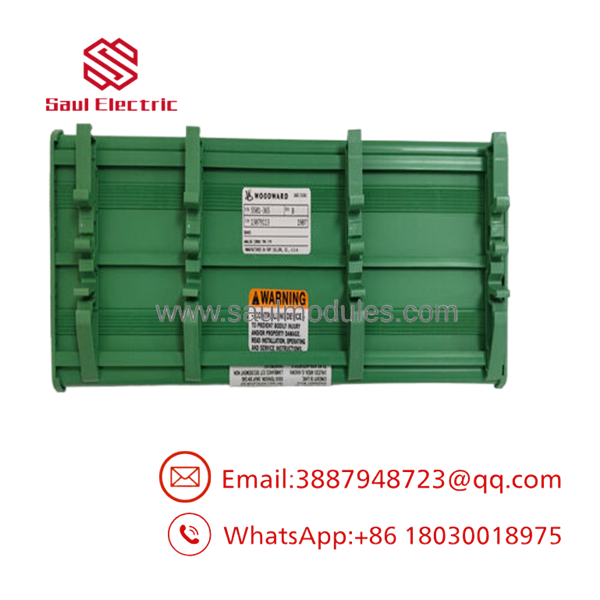
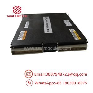
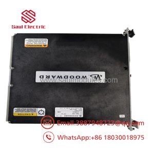
- 5501-365
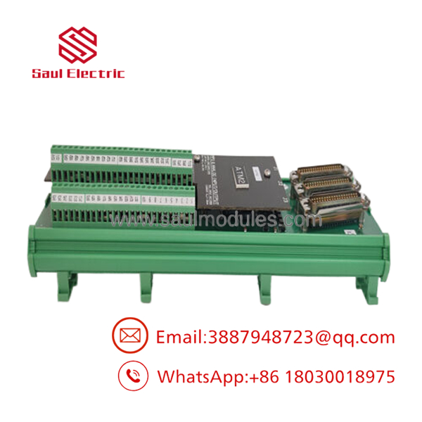
- 5501-365
The Veteran’s Tech Trap Guide (Crucial Value-Add)
⚠️ THE COIL IMPEDANCE TRAP: The 5501-365 is designed with strict compliance voltage limits on its actuator outputs. If you try to wire this card directly to an older, high-resistance third-party actuator coil without verifying the loop resistance, the card will saturate its output early. You will lose the upper end of your valve stroke range and likely throw a constant output fault. Always calculate your total loop resistance (wiring run plus coil resistance) before installation.
PRO TIP: Do not split your MPU speed sensor signals to feed this card and an external standalone overspeed device in parallel unless you are utilizing high-impedance isolation amplifiers. Directly splitting an unshielded MPU line drops the signal amplitude significantly, which can cause the 5501-365 to miss speed pulses at low cranking RPMs.
Dynamic FAQ
Q: Can I use this module to drive a standard voltage-controlled actuator (like 0–10V)? A: No, the 5501-365 is strictly optimized for current-driven proportional applications (such as 4–20 mA or specialized bipolar milliamp ranges). For voltage-controlled actuators, an external current-to-voltage transducer or a different MicroNet analog output module variation is required.
Q: Do you supply the physical terminal blocks that clip into the front of this board? A: Our surplus and refurbished units typically ship as the bare module board assembly. If your existing terminal blocks are damaged or missing, please let our team know during the procurement process so we can source the correct mating connectors for your field wiring.
Q: What is the difference between this model and older revisions of the governor module? A: Component changes across revisions typically involve updated internal component footprints to replace obsolete logic chips. The primary signal pins, software block definitions, and field wiring points remain fully identical and backward compatible.
Q: How do you verify that the internal firmware on this card hasn’t been corrupted? A: During our rack testing phase, the card must establish communication with our diagnostic test CPU and complete its native Power-On Self-Test (POST). If there is any CRC or memory checksum mismatch in the module’s baseline microcode, the board fails our intake process instantly.

 Start Chat


