





Description
Core Product Summary
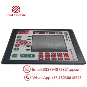
The Woodward EGCP-3 8406-113 is an Engine Generator Control Package configured for load-sharing (LS) applications. It coordinates engine-generator operation in systems where multiple generator sets supply an isolated bus or operate in parallel with a utility mains connection. Its control functions include engine start/stop sequencing, generator synchronization, and load management for parallel-running units.
The controller operates from a nominal 24 VDC supply, with a specified input range of 18–32 VDC. Its measurement and control interfaces include potential-transformer (PT) inputs, current-transformer (CT) inputs, discrete and analog I/O, speed-bias and voltage-bias outputs, and three serial communication ports supporting RS-485, RS-422, and RS-232. In supported multi-generator configurations, the EGCP-3 system can coordinate up to 16 generators for load sharing and associated operating modes.
Key Technical Specifications
| Parameter | Specification |
|---|---|
| Manufacturer | Woodward |
| Model / part number | 8406-113 |
| Product series | EGCP-3 |
| Product type | Engine Generator Control Package |
| Control variant | LS — Load Sharing |
| Nominal supply voltage | 24 VDC |
| Supply operating range | 18–32 VDC |
| Maximum power consumption | 22 W |
| Nominal power consumption | 20 W |
| PT measurement inputs | 27–300 VAC |
| CT measurement inputs | 0–5 A AC RMS nominal; 7 A AC RMS maximum |
| Generator frequency range | 40–70 Hz |
| Magnetic pickup input frequency | 100–24,950 Hz |
| Discrete inputs | 16 |
| Analog inputs | 4–20 mA; 1–5 VDC |
| Analog outputs | 4–20 mA |
| Speed-bias outputs | ±3 VDC; 0.5–4.5 VDC; 5 V peak, 500 Hz PWM; 4–20 mA |
| Voltage-bias outputs | ±1 VDC; ±3 VDC; ±9 VDC; 4–20 mA |
| Discrete outputs | 12 low-side drivers, 200 mA |
| Serial communication ports | 3 × RS-485, RS-422, RS-232 interfaces |
| Operating temperature | −20 to +70°C |
| Storage temperature | −40 to +85°C |
| Humidity | 95% at +20 to +55°C |
| Enclosure protection | IP54 when properly installed in an enclosure rated IP54 or higher |
| Equipment classification | Class I, grounded equipment |
Engineering Selection Highlights
- Load-sharing control variant: The 8406-113 is the LS model, intended for multi-generator load-sharing applications rather than the EGCP-3 MC supervisory-control role.
- Multi-generator coordination: The EGCP-3 architecture supports load sharing among up to 16 generators on a multiple-engine bus, subject to the system configuration.
- 24 VDC control power: The specified 18–32 VDC supply range is an important check when assessing the available control-panel power supply.
- PT and CT measurement inputs: The controller interfaces with generator electrical measurements through voltage and current transformer circuits. Confirm transformer secondary ratings and wiring against the installation documentation.
- Speed and voltage control interfaces: Multiple bias-output formats support integration with compatible engine speed-governing and generator voltage-regulation equipment.
- Serial communications: RS-485, RS-422, and RS-232 interfaces provide options for connecting supported communication devices and control-system components.
- Environmental installation conditions: The specified −20 to +70°C operating range and enclosure-dependent IP54 protection should be considered when designing the installation.
System Compatibility & Integration Requirements
| Item / Dependency | Verified Compatibility or Requirement | Practical Note |
|---|---|---|
| Control system | Woodward EGCP-3 LS architecture | Confirm that the application requires the load-sharing variant, part number 8406-113. |
| DC supply | 24 VDC nominal; 18–32 VDC operating range | Check supply capacity, protection, and wiring before commissioning. |
| Generator voltage measurement | PT inputs, 27–300 VAC | Confirm the voltage measurement circuit and transformer arrangement against the installation drawings. |
| Generator current measurement | CT inputs, 0–5 A AC RMS nominal; 7 A AC RMS maximum | Match the CT secondary rating and protection arrangements to the controller requirements. |
| Engine speed sensing | Magnetic pickup input, 100–24,950 Hz | Verify the sensor signal and operating frequency against the engine speed-sensing arrangement. |
| Governor interface | Supported speed-bias output formats | Match the configured output type to the connected governor’s electrical input requirements. |
| Voltage regulator interface | Supported voltage-bias output formats | Check the AVR input range and control method before connecting the bias output. |
| Communications | RS-485, RS-422, and RS-232 | Confirm interface type, wiring, network topology, and protocol configuration for the intended equipment. |
| Generator paralleling | Isolated-bus or utility-parallel applications | Independent synchronism-check and protective relay arrangements are required as specified by the system design and applicable installation practices. |
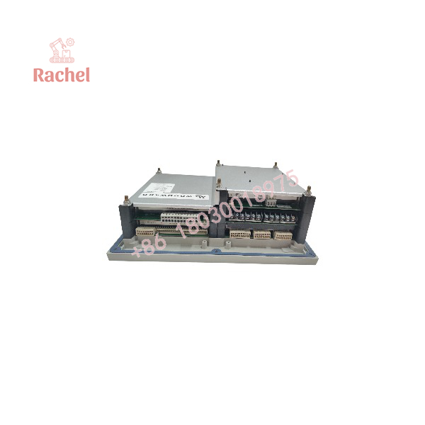
EGCP-3 8406-113
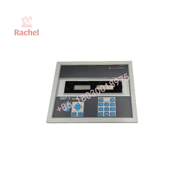
EGCP-3 8406-113
Dimensions, Mounting & Connection Notes
- Installation format: Panel-mounted engine-generator control package.
- Approximate overall dimensions: 282 × 358 × 134 mm (H × W × D).
- Power connection: Nominal 24 VDC control supply.
- Electrical measurement connections: PT and CT inputs use dedicated measurement terminals.
- Control wiring: Includes discrete inputs and outputs, analog I/O, speed-bias outputs, and voltage-bias outputs.
- Communication wiring: Three serial communication interfaces supporting RS-485, RS-422, and RS-232.
- Grounding: Protective earth must be connected to the designated grounding point using a correctly sized conductor and suitable termination.
- Installation protection: The IP54 protection level applies when the controller is correctly installed in an enclosure rated IP54 or higher.
Use the applicable installation manual for terminal assignments, wiring diagrams, fuse requirements, grounding, clearances, and commissioning procedures. Generator voltage and current circuits can present hazardous conditions and must be handled by qualified personnel.
Detailed Product Overview
Load-sharing control for engine-generator systems
The Woodward EGCP-3 8406-113 is the LS (Load Sharing) version of the EGCP-3 Engine Generator Control Package. Its purpose is to coordinate generator operation where several engine-driven generator sets supply a common isolated bus or operate in parallel with a utility supply.
Engine-generator coordination involves more than starting and stopping engines. The control system must account for generator electrical measurements, engine speed, voltage regulation, breaker conditions, and the operating mode required by the power system. The EGCP-3 LS combines these control responsibilities within the generator-control architecture.
Generator measurement and control interfaces
The controller provides PT inputs for voltage measurement and CT inputs for current measurement. These signals supply electrical information needed by the control system. Correct selection of the measurement transformers and associated wiring is essential because the controller input ratings define the permissible electrical interface.
Speed-bias and voltage-bias outputs provide interfaces to compatible governor and voltage-regulator equipment. The available output formats include analog current and voltage signals and a PWM speed-bias option. The correct interface must be selected according to the connected equipment’s documented input requirements and the configured control application.
I/O and communications
The 8406-113 includes discrete inputs, discrete outputs, analog inputs, analog outputs, and three serial communication ports. These interfaces allow the control package to receive external status signals, provide control outputs, and communicate with compatible devices in the generator-control system.
The serial interfaces support RS-485, RS-422, and RS-232 electrical standards. These standards describe different communication interfaces; the required wiring, protocol, and network configuration depend on the connected equipment and system design.
Power-system operating modes
The EGCP-3 LS supports isochronous speed control for isolated-bus operation and can coordinate multiple generators in load-sharing, BaseLoad, or process-control modes. The system can support up to 16 generators in a multiple-engine bus configuration.
The applicable mode depends on the power-system arrangement and the controller configuration. Commissioning therefore requires the correct system parameters, compatible governor and voltage-regulator interfaces, suitable breaker-control arrangements, and independent protective devices.
Installation and engineering considerations
The controller requires a nominal 24 VDC supply within its specified operating range. Its PT and CT circuits, external control signals, grounding, and communication connections must be installed in accordance with the relevant technical documentation.
Environmental suitability also matters. The specified operating temperature is −20 to +70°C, and the stated IP54 protection is conditional on installation in a suitably rated enclosure. Panel design should account for the physical dimensions, terminal access, cable routing, grounding, and servicing requirements.
Applications & System Role
The Woodward EGCP-3 8406-113 serves as the load-sharing controller within an engine-generator control architecture. It combines generator monitoring, engine sequencing, synchronization-related control, and load management functions in a single control package.
Its principal application is a power system containing multiple generator sets that must operate together. In an isolated-bus arrangement, the controller supports isochronous speed control. In a multi-generator installation, the control system can coordinate load sharing and support BaseLoad and process-control operating modes. The EGCP-3 LS is also designed for applications in which generators operate in parallel with a utility mains bus.
Typical engineering fit scenarios include:
- Parallel generator plants: Coordinate multiple generator sets supplying a common electrical bus.
- Stand-alone generation systems: Support engine start/stop sequencing and generator control for isolated-bus operation.
- Utility-parallel generation: Support generator operation alongside a mains supply within a properly engineered synchronization and protection system.
- Generator control panels: Integrate voltage and current measurements, speed-governor interfaces, voltage-regulator interfaces, and serial communications.
- Multi-unit load management: Coordinate load sharing and associated operating modes across a configured EGCP-3 generator-control network.
The controller is part of a broader electrical protection and control arrangement. Independent overspeed shutdown, synchronism-check, circuit-breaker, and other required protective functions must be provided as appropriate to the installation. The EGCP-3 should not be treated as a substitute for independently required protective equipment.
FAQ
What is the Woodward EGCP-3 8406-113?
It is a Woodward Engine Generator Control Package in the LS (Load Sharing) configuration, designed for coordinated operation of engine-driven generator sets.
What is the difference between the EGCP-3 LS and its MC variant?
The LS model performs generator-level load-sharing and control functions. The MC model serves a supervisory role, coordinating system-level functions alongside EGCP-3 LS units in supported configurations.
How many generators can an EGCP-3 system coordinate?
The documented EGCP-3 multi-generator architecture supports up to 16 generators on a multiple-engine bus. The actual arrangement depends on the system configuration and application requirements.
What power supply does the 8406-113 require?
It uses a nominal 24 VDC supply with a specified operating range of 18–32 VDC. The documented maximum power consumption is 22 W.
Which communication interfaces are available?
The controller provides three serial communication ports supporting RS-485, RS-422, and RS-232 interfaces. The communication configuration must match the connected equipment.
What are the PT and CT input ratings?
The documented PT input range is 27–300 VAC. The CT inputs are rated for 0–5 A AC RMS nominal, with a maximum input of 7 A AC RMS. Transformer selection and wiring must follow the installation requirements.
What is the operating temperature range?
The specified operating temperature range is −20 to +70°C. The specified storage temperature range is −40 to +85°C.
What protection is required when using the EGCP-3 8406-113?
The installation must provide the grounding, fusing, enclosure protection, and independent generator protection required by the applicable design and installation instructions. Synchronism-check and overspeed protection must not depend solely on the prime-mover control system.

 Start Chat


