





Description
Core Product Summary
The Woodward ESDR 4 is a microprocessor-based current differential protection relay designed to detect electrical faults within a defined protection zone. It compares measured phase currents at the boundaries of the protected equipment and initiates tripping when the differential current exceeds configured protection thresholds.
The relay supports three-phase differential protection for interconnected electrical equipment, including generators and motors. It provides configurable monitoring thresholds, time delays, discrete control inputs, and relay outputs. The unit operates from a 24 VDC supply and accepts current-transformer inputs rated for 1 A or 5 A secondary circuits, depending on the ordered version. Mounting and current-input variants must be matched to the installation.
Key Technical Specifications
| Parameter | Specification |
|---|---|
| Manufacturer | Woodward |
| Product series | ESDR 4 |
| Product type | Current differential protection relay |
| Protection function | Three-phase current differential protection |
| Measuring inputs | Six current inputs |
| Rated CT secondary current | 1 A or 5 A, depending on version |
| Measuring frequency | 40–70 Hz |
| Current measurement accuracy | Class 1 |
| Power supply | 24 VDC, ±25% |
| Maximum power consumption | 6 W |
| Isolated discrete inputs | 18–250 VAC/DC |
| Relay outputs | Four isolated relay outputs |
| Operating temperature | −20 to +70 °C |
| Relative humidity | Up to 95%, non-condensing |
| Front-panel mounting dimensions | 144 × 72 × 199 mm (W × H × D) |
| Enclosure protection | IP21 |
| Approximate weight | 1,000 g |
Engineering Selection Highlights
- Differential protection: Compares currents across a defined protection zone to detect internal electrical faults.
- Configurable trip thresholds: Adjustable protection characteristics allow settings to be coordinated with the protected equipment and protection scheme.
- CT input selection: Available 1 A and 5 A input versions require matching current-transformer secondary ratings.
- 24 VDC supply: The control cabinet must provide a suitable DC supply within the specified voltage range.
- Isolated control inputs: The discrete inputs support external configuration, blocking, and acknowledgement functions.
- Relay-based signaling: Output contacts provide operational status and protection-trip signaling to associated equipment.
- Mounting options: Front-panel and DIN-rail versions are available within the ESDR 4 product family; the exact order code determines the required installation arrangement.
System Compatibility & Integration Requirements
| Item | Requirement | Engineering consideration |
|---|---|---|
| Current transformers | 1 A or 5 A secondary rating | Match the relay input version to the installed CT secondary circuits. |
| Auxiliary power | 24 VDC, ±25% | Confirm supply polarity, wiring, and available cabinet power. |
| Protection zone | Current measurements at the relevant boundaries | Follow the protection scheme and relay wiring documentation. |
| Trip circuit | External circuit-breaker or trip-control interface | Confirm contact logic and trip-circuit ratings before commissioning. |
| Control inputs | 18–250 VAC/DC | Ensure the external control voltage is within the permitted range. |
| Mechanical mounting | Front-panel or DIN-rail configuration | Confirm the exact hardware version and available installation space. |
Dimensions, Mounting & Connection Notes
The front-panel version has published overall dimensions of 144 × 72 × 199 mm. DIN-rail mounting versions are also available under separate product numbers.
Installation considerations include:
- Use the wiring diagram applicable to the exact ESDR 4 version.
- Match each current-transformer secondary circuit to the relay’s rated input.
- Observe the specified grounding arrangement for current-transformer secondary circuits.
- Provide an accessible circuit-isolating device near the relay.
- Follow electrical safety procedures during installation, testing, and commissioning.
Important: Never disconnect a current-transformer secondary circuit while its primary circuit is energized unless an approved procedure ensures that the secondary is safely short-circuited. Dangerous voltages can develop in an open CT secondary circuit.
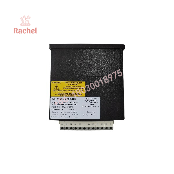
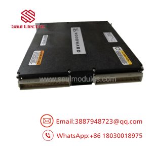
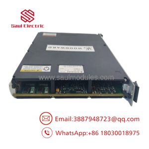
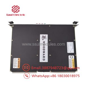
ESDR4
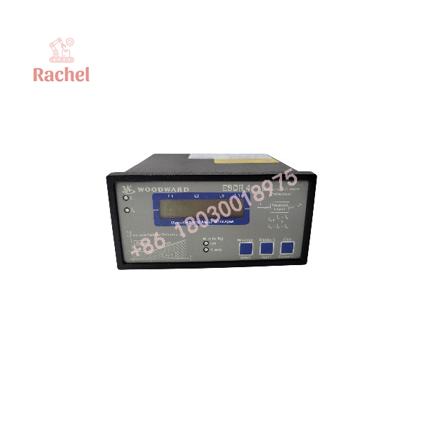
ESDR4
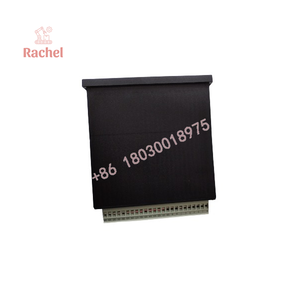
ESDR4
Applications & System Role
The Woodward ESDR 4 occupies the protection layer of an electrical power system. It monitors current measurements from the protected equipment and evaluates whether the measured differential current indicates an internal fault.
Its primary function is to distinguish faults within the designated protection zone from faults outside that zone. This selectivity allows the protection system to trip the affected equipment without unnecessarily disconnecting unrelated sections of the electrical installation.
Typical documented equipment contexts include:
- Generators: Differential protection against internal winding and phase faults.
- Electric motors: Monitoring current differences across the protected motor circuit.
- Interconnected electrical equipment: Protection of equipment where current measurements are available at the relevant boundaries.
The relay’s adjustable characteristics allow protection settings to be coordinated with the protected equipment and associated circuit-breaker scheme. Correct current-transformer selection, polarity, wiring, and configuration are essential to the intended protection behavior.
Detailed Product Overview
Differential current measurement
The ESDR 4 evaluates the difference between currents measured at the boundaries of a protected zone. Under normal operating conditions, the measured currents should satisfy the relationship established by the protection scheme. A significant difference can indicate an internal fault.
The relay uses configurable monitoring stages. The first stage can provide a warning when the differential current exceeds its configured threshold. A higher-level condition can initiate a trip, depending on the configured protection characteristics.
Configuration and control
The front-panel interface provides access to operating values and configuration parameters. Settings include differential-current monitoring characteristics and associated time delays. External discrete inputs support control functions such as configuration selection, blocking, and acknowledgement.
Correct configuration depends on the protected equipment, current-transformer ratios, wiring arrangement, and required trip behavior. Settings should be established and tested as part of the site’s protection-coordination process.
Electrical integration
The ESDR 4 uses a 24 VDC auxiliary supply and accepts isolated discrete input signals across a broad AC/DC voltage range. Its relay outputs interface with external signaling or tripping circuits, subject to the specified contact ratings and the requirements of the connected equipment.
Before commissioning, verify the selected current-input rating, CT wiring, phase correspondence, trip logic, and configured protection thresholds. Commissioning tests should demonstrate that the relay responds correctly to faults within the protected zone while maintaining the intended discrimination for external faults.
Ordering and replacement considerations
The designation ESDR 4 covers multiple hardware configurations. The correct order number depends on the current-transformer input rating and mounting arrangement.
Published order-code examples include:
| Configuration | Product number |
|---|---|
| Front-panel mounting, 1 A | LR20459 |
| DIN-rail mounting, 1 A | 8441-1105 |
| Front-panel mounting, 5 A | 8441-1010 |
| DIN-rail mounting, 5 A | LR20590 |
These numbers identify specific ESDR 4 variants. Confirm the complete part number on the installed unit before ordering a replacement.
FAQ
1. What is the Woodward ESDR4?
The Woodward ESDR 4 is a microprocessor-based current differential protection relay for detecting electrical faults within a defined protection zone.
2. What equipment can the ESDR 4 protect?
Its documented application scope includes generators, motors, and interconnected electrical equipment requiring differential protection.
3. What power supply does the ESDR 4 require?
It requires a 24 VDC auxiliary supply with a permitted range of ±25%.
4. Does the ESDR 4 support both 1 A and 5 A current transformers?
Yes. Separate versions support 1 A or 5 A CT secondary circuits. The relay’s input rating must match the installed CTs.
5. What is the difference between ESDR 4 and ESDR 4T?
The ESDR 4T adds transformer-specific configuration functions, including configurable transformer ratio and vector group. These functions should not be assumed to be available on the standard ESDR 4.
6. What mounting options are available?
The product family includes front-panel and DIN-rail mounting variants, each with its own order number.
7. What should be checked when replacing an ESDR 4?
Check the complete part number, CT secondary rating, mounting arrangement, auxiliary supply, terminal wiring, and configured protection settings before replacement or commissioning.

 Start Chat


