





Description
Product Introduction & Engineering Value
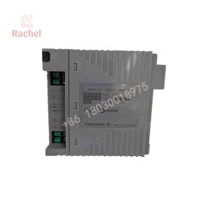
The Yokogawa ADV551-P50 provides 32 discrete transistor-sink outputs for field devices connected to a Yokogawa distributed control system. Unlike a basic on/off DO card, its P-function configuration supports pulse-width and time-proportional output, making it applicable to control functions where output duration or duty cycle matters.
For replacement work, the important details are the complete suffix and connection option, not just ADV551-P50. A /D5A00, /D5S00, or another connection configuration can require different external wiring hardware. The field connection should therefore be compared against the original module and cabinet drawings before installation.
Technical Specifications
| Specification | ADV551-P50 |
|---|---|
| Module type | Digital output |
| Number of channels | 32 |
| Output technology | Transistor contact / current sink |
| Rated load voltage | 24 VDC |
| External field supply | 20.4–26.4 VDC |
| Maximum load current | 50 mA/channel |
| Output function | Status output |
| Additional output function | Pulse-width output |
| Additional control function | Time-proportional output |
| Pulse-width range | 8 ms to 7,200 s |
| Pulse-width resolution | 8 ms |
| Status-output response | ≤3 ms |
| Mixed status/pulse response | ≤10 ms |
| Module weight | Approximately 0.2 kg |
| Typical connection option | /D5A00, ATD5A-00 KS cable adapter |
The pulse-width range and response figures are documented in current ADV551-P50 product references.
Output Architecture
The ADV551-P50 uses current-sink transistor outputs. That distinction matters when checking field wiring: the module is not equivalent to a source-type digital output card simply because both operate with nominal 24 VDC field circuits.
The documented electrical isolation includes a 2 kVAC withstand specification between signal and system circuitry and a 500 VAC common-to-common withstand specification in the referenced configuration.
How the ADV551-P50 Works in a DCS
The module sits in the Yokogawa FIO architecture and converts DCS output commands into discrete electrical switching signals.
A simplified control path is:
DCS control logic → FIO communication → ADV551-P50 → transistor sink output → field load
Typical loads include:
- Interposing relays
- Solenoid valves
- Pilot devices
- Status lamps
- Contactors through suitable interfaces
- Other 24 VDC discrete loads
The P-function also permits pulse-width and time-proportional control, which can be useful for applications such as dosing, heating control, and other duty-cycle-based functions.
Field Application & Trench Experience
A typical maintenance situation occurs on a legacy Yokogawa DCS where one digital-output channel begins showing intermittent operation. The field actuator may work during a cabinet test but fail when the load is connected. Replacing the module without checking the field supply and load current can result in the same symptom returning immediately.
For the ADV551-P50, a useful troubleshooting sequence is:
- Verify the external 24 VDC field supply.
- Measure voltage at the module under load.
- Confirm the field device current does not exceed the channel rating.
- Check the common wiring.
- Verify the DCS channel assignment.
- Confirm the correct cable/terminal adapter.
- Test the output with a known-good load.
Niche Application Scenarios
Solenoid valve control
The transistor outputs can switch compatible 24 VDC solenoid circuits through the appropriate field interface.
Time-proportional process control
The P-function is useful where the control strategy requires defined output durations rather than only binary ON/OFF operation.
High-density DCS cabinets
Thirty-two output channels in one module provide a relatively high channel density for distributed discrete control.
QA & Testing SOP
New Surplus Inspection
For a Nelus , verify:
- Complete model designation
- Suffix and style code
- Manufacturer markings
- Serial number
- PCB revision where visible
- Connector arrangement
- Physical condition
- Original packaging, when available
- Storage condition
A photograph showing only the front of the module is not sufficient to establish the exact connection configuration.
Electrical Testing
A practical inspection procedure should include:
1. Visual inspection
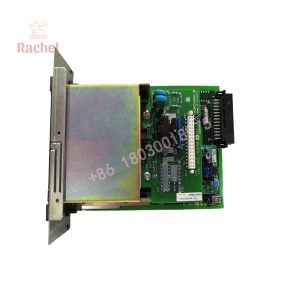
Check the housing, PCB, connectors, labels, and terminal/cable interface.
2. Supply verification
Apply the specified system and field supplies using controlled laboratory equipment.
3. Output verification
Command representative channels and confirm correct transistor switching.
4. Load test
Use a controlled load rather than relying only on an open-circuit voltage measurement.
5. Pulse test
For the P-function, verify that pulse-width operation follows the configured timing.
6. Diagnostic verification
Confirm normal communication and module status through the compatible Yokogawa control system.
New Surplus vs. Refurbished
New Surplus means the unit is unused surplus inventory and may have been stored outside the current OEM distribution chain.
Refurbished means the unit has previously been used or otherwise requires reconditioning and has been inspected/tested before resale.
The supplier should state the actual condition rather than using “new” generically for both categories.
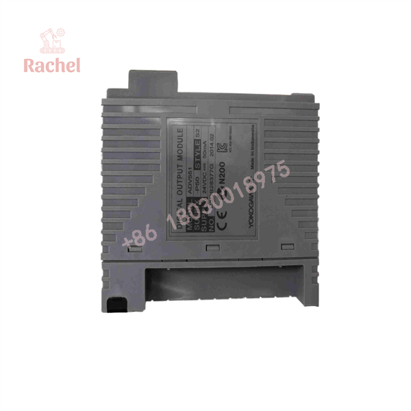
ADV551-P50
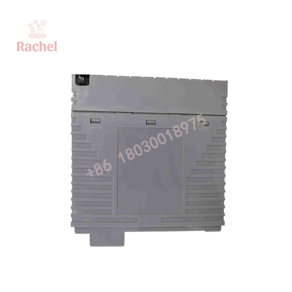
ADV551-P50
Veteran’s Tech Trap Guide
⚠️ Trap 1: Confusing ADV551-P50 with ADV561
The ADV551 family is a sink-type digital output architecture. Do not substitute a source-type output module simply because it has the same channel count and nominal voltage.
The field circuit must match the output topology shown in the Yokogawa engineering documentation.
⚠️ Trap 2: Ignoring the connection option
and /D5A00 should not automatically be treated as identical purchasing descriptions.
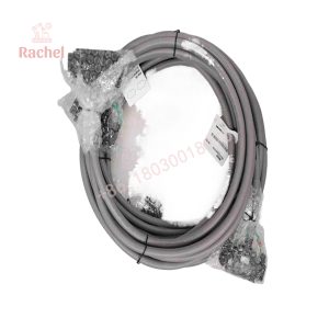
The /D5A00 configuration specifically includes the ATD5A-00 KS cable interface adapter. Other connection options use different physical interfaces.
⚠️ Trap 3: Treating 24 VDC as the complete electrical specification
The field supply is documented as 20.4–26.4 VDC in the referenced configuration. Check the actual field power supply and voltage at the module terminals, especially when long cable runs or multiple actuators share the supply.
PRO TIP: Check the actual load current
A field device that draws more current than the permitted channel rating can cause output problems even when the DCS logic and module diagnostics appear normal.
For the referenced P50 configuration, the documented maximum is 50 mA per channel. Do not use a higher current figure from a different ADV551 variant without confirming the exact suffix and revision.
⚠️ Trap 4: Assuming every P50 listing has the same environmental specification
Some commercial listings describe different ADV551-P50 suffix configurations, including S1/S2 and /D5A00 or /D5S00. Environmental and connection characteristics can differ between these configurations. Match the complete ordering code before using a specification from another variant.
FAQ
What is the Yokogawa ADV551-P50?
The is a 32-channel digital output module for Yokogawa DCS/FIO applications. It uses transistor current-sink outputs and supports status, pulse-width, and time-proportional output functions.
How many outputs does ADV551-P50 provide?
It provides 32 digital output channels. The documented module uses a 24 VDC field supply and transistor-sink output architecture.
What does the “P” in ADV551-P50 mean?
The P functional suffix identifies the version with pulse-width and time-proportional output functionality.
What is the differenand /D5A00?
/ identifies a connection configuration that includes the ATD5A-00 KS cable interface adapter. The base module designation alone does not fully describe the external wiring arrangement.
What type of output does the ADV551-P50 use?
The documented P50 configuration uses transistor-contact, current-sink outputs. This is important when determining whether an existing field load and wiring scheme are electrically compatible.
Is the ADV551-P50 suitable for pulse control?
Yes. The P-function supports pulse-width and time-proportional output. Current documentation gives a pulse-width range of 8 ms to 7,200 seconds, with an 8 ms resolution.
Is a New Surplus ADV551-P50 genuine Yokogawa equipment?
New Surplus should mean unused original equipment, but the term itself does not prove authenticity. Verify the Yokogawa markings, complete model code, serial information, connector configuration, and physical construction. For a high-value DCS spare, supplier traceability and test records are useful additional evidence.
What warranty should I expect?
Warranty depends on the supplier and stock condition. Before purchasing, confirm the warranty duration, DOA policy, return conditions, and whether the specific module was electrically tested. For New Surplus stock, ask whether the unit has been previously energized or installed.

 Start Chat


