





Description
Key Technical Specifications
| Parameter | Value |
| Product Type | Isolated Power Supply Module (IPS) |
| Model Designation | IPS 21-35 AD |
| Input Voltage Range | 90…264 V AC (or nominal 100…240 V AC, 50/60 Hz) |
| Output Voltage | 24 V DC (Regulated, highly stable) |
| Output Current | 1 A |
| Output Ripple & Noise | < 1% peak-to-peak |
| Isolation Voltage | 3,000 V RMS (between input and output channels) |
| Efficiency | > 90% at nominal loads |
| Mounting Style | Internal rack mount / subprint integration |
| Physical Dimensions | 100 mm x 60 mm x 25 mm (approximate board footprint) |
| Product Net Weight | 0.25 kg (0.55 lbs) |
| Operating Temperature | -25 to +55 °C |
Product Introduction
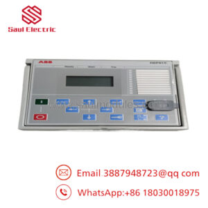
The ABB IPS 21-35 AD (3BHB017688R0001) is a specialized, industrial-grade isolated power supply module engineered specifically to provide clean, isolated, and regulated DC power to critical DCS processing loops, excitation controllers, and sensitive communication modules. It excels at suppressing electrical noise, line surges, and common-mode transients from reaching delicate control-level microprocessors.
With a wide input voltage range of 90…264 V AC and a robust 3,000 V RMS galvanic isolation rating, this compact module is ideal for deployment in harsh electrical environments like power generation plants, heavy manufacturing facilities, and marine propulsion control cabinets. The unit protects your core controller modules from ground loops and high-frequency interference, maximizing overall system uptime.
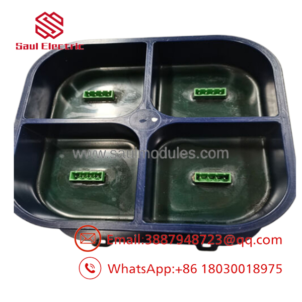
- 3BHB017688R0001
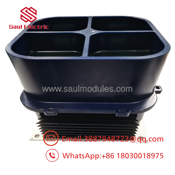
- 3BHB017688R0001
Installation & Configuration Guide
Stage 1: Pre-Installation Preparation (Estimated Time: 10 minutes)
- ⚠️ Safety First: Isolate and lock out the AC mains power feeding the power distribution panel. Verify that zero voltage is present on the incoming wiring terminal strips using a trusted multimeter before making contact with the electrical connections.
- Tools Required: Grounded anti-static (ESD) wrist strap, small flathead terminal screwdriver, cross-tip screwdriver, multimeter, wire labels.
- Data Backup: While replacing this isolated power supply does not delete software programs directly, any controller connected to it will go dark. Coordinate with operations to place connected processes into a safe, manual state before removing power.
Stage 2: Removing the Old Module (Estimated Time: 5 minutes)
- Verify the input AC power supply leads are completely dead using your multimeter.
- Unplug the AC input terminal block connector and the 24 V DC output plug. Mark the cables clearly to prevent polarity reversal during installation.
- Remove the mounting screws holding the IPS board bracket to the panel plate or release the mounting tabs if integrated into a carrier subprint.
- Carefully pull the module out of its slot, handling it strictly by the housing edges.
- ⚠️ Note: Place the old power supply module on an ESD-safe mat. Keep it for physical dimension and layout comparison until the new unit is confirmed functional.
Stage 3: Installing the New Module (Estimated Time: 10 minutes)
- Ensure you are wearing a grounded ESD wrist strap before handling the replacement 3BHB017688R0001 board.
- Align the module card with the mounting holes or guide rails inside the controller cabinet slot.
- Secure the module in place using its native mounting screws. Ensure the board is mounted firmly to prevent issues from cabinet vibrations.
- Reconnect the 24 V DC output terminal wiring first, paying strict attention to polarity: +24 V DC (Positive) and 0 V DC (Negative/Common).
- Reconnect the incoming AC main leads (L, N, and Protective Earth Ground) to the input terminals.
Self-Checklist:
- [ ] AC and DC terminal screws torqued to spec
- [ ] Earth ground wire securely bonded to the chassis
- [ ] Clean air clearance around the vent openings
Stage 4: Power-On & Testing (Estimated Time: 10 minutes)
- Double-check all terminal connection paths for accidental shorts.
- Switch on the upstream AC mains breaker to energize the IPS 21-35 AD unit.
- Verify the LED indicators:
- Power/Status LED: Solid Green (indicating stable 24 V DC output).
- Fault LED: Off (If red or flashing, shut off power and check for DC-side short circuits).
- Using your multimeter, measure the DC output voltage directly across the terminal screws. It must read between 23.8 V and 24.2 V DC.
- ⚠️ Troubleshooting Note: If the output voltage reads zero, immediately remove input power and verify that the output loop current does not exceed the unit’s maximum rating of 1 A. Over-current conditions will trip the internal electronic fold-back protection.
Frequently Asked Questions (FAQ)
Can the IPS 21-35 AD (3BHB017688R0001) handle loads above 1 A?
No. The IPS 21-35 AD is designed for high-isolation, low-noise control loops and has a strict maximum continuous output current rating of 1 A. Exceeding this rating will cause the module to enter over-current protection mode, which drops the output voltage to prevent thermal damage. For heavier loads, you must distribute your device connections across multiple isolated modules.
Why is this unit called an “Isolated” power supply, and why is that important?
Unlike a standard industrial power supply, the IPS 21-35 AD features an isolation transformer and optoelectronic barriers that provide 3,000 V RMS galvanic isolation between the input and output lines. This means there is no direct electrical path between your noisy plant AC power grid and your highly sensitive DCS processors, preventing dangerous ground loop currents and transient spikes from damaging downstream microchips.
Is this power supply unit hot-swappable?
No. Changing this module while the electrical terminal lines are hot is highly discouraged. Doing so can cause electrical arcs on the AC terminals or spike the DC bus, which may crash the connected controllers. Always turn off the upstream power source before performing a hardware swap.
What causes these power supplies to fail prematurely in the field?
The most common causes of failure in these power modules are prolonged exposure to ambient temperatures above 55 °C, excessive dust accumulation on the components (which blocks natural cooling), and persistent overloading close to the 1 A limit. Ensure your control enclosures have adequate ventilation and clean air filtration.
Why is there a difference between the weight listed on some surplus sites and the actual module weight?
The bare IPS 21-35 AD module weighs approximately 0.25 kg. However, shipping weight is often listed around 2 to 3 kg on various B2B parts websites. This discrepancy is due to heavy-duty protective industrial packaging, double-walled boxes, and anti-static padding used to ensure the component arrives safely without taking damage from transit vibrations.


 Start Chat


