





Description
Key Technical Specifications
| Parameter | Value |
| Brand | ABB |
| Part Number | 3BHE037864R0104 |
| Type Designation | UF C911 B104 / CVMI2B |
| Channel Count | 32 Analog Channels |
| Analog Input Ranges | ±10 V, ±20 mA |
| Analog Output Ranges | ±10 V, ±20 mA |
| Measurement Accuracy | 0.1% full scale |
| Response Time | Less than 2 ms |
| Standards Compliance | IEC 61131-2 |
| Operating Temperature | -10 to +70 °C |
| Storage Temperature | -40 to +80 °C |
| Net Weight | 0.2 kg |
| Dimensions (W x H x D) | 225 mm x 66 mm x 112.5 mm |
Product Introduction
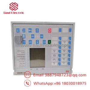
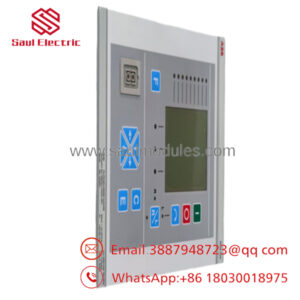
The ABB 3BHE037864R0104, designated as type UF C911 B104 (CVMI2B), is a high-density analog I/O interface board built for ABB medium-voltage drives and Unitrol excitation control loops. It processes multi-channel analog signals to maintain precise control regulation in demanding industrial environments.
Engineers select this board for its 0.1% measurement accuracy and rapid sub-2 ms response times during high-power switching applications. It serves as a direct drop-in replacement card for systems requiring immediate mechanical and electrical backplane compatibility.
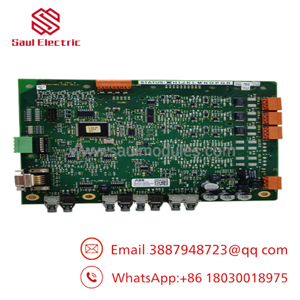
- 3BHE037864R0104
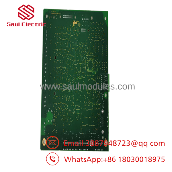
- 3BHE037864R0104
Installation & Configuration Guide
1.Pre-Installation Preparation:Estimated time: 10 mins.
Identify and isolate. Notify operations of planned system downtime. Verify the drive or excitation system is in a completely safe, unpowered state. Follow standard lock out/tag out (LOTO) protocols on the main breaker.
⚠️ Capacitor Discharge Warning: Wait at least 5 minutes for internal drive capacitors to discharge completely before opening the housing.
Gather your tools: a grounded ESD wrist strap, a PH1 screwdriver, a Fluke 115 multimeter, wire labels, and a smartphone. Before proceeding, connect to the system software to document current hardware parameters and verify the existing board’s firmware range.
2.Removing the Old Module:Estimated time: 5 mins.
Attach your grounded ESD wrist strap to the rack chassis. Unclip the front cover bezel to expose the circuit plate. Take a clear photograph of the current terminal wiring and physical jumper arrangements. Label every wire clearly before removal.
Disconnect the terminal connectors carefully; do not pull on the wires directly. Loosen the retention screws or release the DIN rack locking tabs. Pull the module straight out from the slot to avoid bending or snapping the sensitive backplane pins. Inspect the bare slot for dust accumulation or visual damage. Keep the old module nearby for hardware cross-reference.
3.Installing the New Module:Estimated time: 10 mins.
Unpack the new 3BHE037864R0104 board inside an ESD-safe zone. Confirm the model number and revision suffixes align with your system configuration requirements.
Configuration Clone: Replicate all physical DIP switches and onboard hardware jumpers from the old module using the photograph you took. Pay critical attention to bus termination resistors and individual node addressing blocks.
Align the module with the rack guides and slide it smoothly into the slot until you feel it seat into the backplane connector. Fasten the locking tabs securely. Reattach the labeled wiring terminals using a torque-appropriate screwdriver to ensure solid electrical contact without crushing the terminals.
Self-Checklist:
- [ ] DIP switches and node address jumpers match the old card layout exactly.
- [ ] Wiring blocks are fully seated with zero exposed copper strands.
- [ ] Module retention clips are engaged and locked into the chassis slot.
4.Power-On & Testing:Estimated time: 15 mins.
Before energizing, use your multimeter to check for any dead shorts on the 24 V rail. Ensure the rack backplane power budget accommodates the draw with a 20% safety margin. Apply power to the controller rack only, leaving field devices isolated.
Observe the startup LED sequence. A green RUN or OK LED indicates a successful boot cycle. Connect your programming tool to verify the board is recognized on the bus, checking that the node address and firmware match. Perform a point-to-point dry-run verification on the analog loops before returning the system to live operation.
⚠️ Troubleshooting Note: If the red ERR LED turns solid, suspect a firmware revision mismatch between the new module and the master controller. If communication fails entirely, re-verify the node address settings on the physical DIP block.
Frequently Asked Questions (FAQ)
Q: Can the ABB 3BHE037864R0104 board be hot-swapped while the drive system is powered?
A: No, it cannot. Attempting to hot-swap this specific analog interface card under live power risks inducing transient voltage spikes. This can permanently damage the backplane bus or fry the onboard ASIC chips. Always drop control and main power to the rack, verify it is dead with a multimeter, and wait 5 minutes for the internal capacitors to drain before inserting or removing the hardware.
Q: This model is noted as obsolete by the factory. Is your inventory genuinely new?
A: Yes, these units are New Original Surplus (New Surplus). They have never been fielded or installed in a production environment. They are sourced from excess corporate capital spares or cancelled plant expansion projects. While the outer factory box may exhibit shelf wear, scuffs, or logistics labels, the internal board remains factory-clean and is verified functional under load testing.
Q: What happens if the replacement board has a newer firmware revision than my old one?
A: This is a common pitfall that stalls commissions. If the replacement module firmware version is too advanced for your controller’s current base software, the master PLC or drive controller will likely flag a communication timeout error. Before installation, document the firmware sticker on both the old and new cards. If you see a major revision jump, you must update your hardware profile configuration within the control software to accommodate the new protocol definitions.
Q: Will pulling this circuit plate cause me to lose my underlying drive programming or logic?
A: No. The 3BHE037864R0104 functions strictly as an analog I/O interface board (circulation plate). It does not house the primary application runtime logic, variables, or volatile controller memory. Your application code resides safely in the main CPU or drive control processor. However, you must copy the physical jumper configurations and DIP switch addresses so the controller can communicate with the new card on boot.
Q: Why is your price for this genuine ABB module lower than the standard factory list price?
A: We buy this equipment out of surplus inventory, corporate liquidations, and cancelled utility projects rather than ordering directly through the manufacturer’s standard distribution network. Because we skip the traditional dealer supply chains, we can pass those direct capital savings onto maintenance teams and system integrators. The hardware is identical, genuine ABB stock.
Q: What is the direct replacement if this specific part number goes completely out of stock?
A: The exact substitute depends heavily on your system frame size and application (such as an ACS1000 drive versus a Unitrol 6000 excitation loop). ABB utilizes distinct revisions within this family, including the R0106 and R0110 variants. Do not substitute revisions blindly from memory; always verify the suffix and revision level against your actual electrical engineering schematics before purchasing an alternative part number.

 Start Chat


