





Description
Key Technical Specifications
| Parameter | Specification Value |
|---|---|
| Housing Design | 19-inch rack-mount chassis, 4 U height profile |
| Module Capacity | Fits up to 4 internal plug-in analyzer modules (e.g., Uras26 IR, Limas21 UV, Magnos206 O2) |
| Power Supply | 100 to 240 V AC (± 10%), 50 to 60 Hz (± 3 Hz) |
| Power Consumption | Maximum 187 VA (mainframe plus fully loaded modules) |
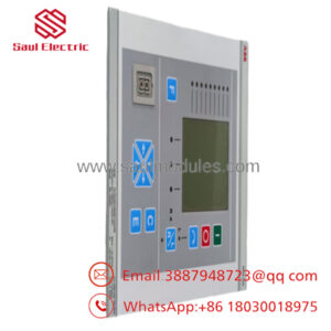
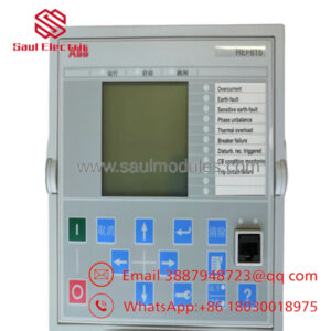
| Display Panel | Backlit graphic LCD screen, 320 x 240 pixel resolution |
| Operator Inputs | 10-key numerical keypad paired with 8 dynamic softkeys |
| Digital Communication | 10/100 Base-T Ethernet (TQP/IP), Modbus TCP/RTU, Profibus DP (optional) |
| Analog Outputs | Up to 4 isolated 0/4 to 20 mA outputs per internal detector module |
| Digital I/O Board | Expandable relay outputs and optocoupler inputs for threshold limits and system faults |
| Enclosure Rating | IP20 front and rear terminal boundary sealing (standard rack configuration) |
| Ambient Temperature | +5 to +45 °C (+41 to +113 °F) during operational cycles |
Product Introduction
The ABB AO2020 is the centralized mainframe engine of the Advance Optima series continuous gas analyzer platform. Rather than serving as a single-gas standalone device, the AO2020 acts as a modular processing framework designed to simultaneously house, power, and coordinate multiple photometer, electrochemical, or paramagnetic sensor modules. This hardware configuration allows plants to track multiple discrete chemical compounds—such as CO, CO2, SO2, NO, and O2—from a single physical sample stream line.
Operating as an intelligent communication gateway, the AO2020 aggregates raw digitized diagnostic data from its integrated analytical modules and delivers real-time concentration variables across industrial Ethernet or Modbus protocols straight to CEMS (Continuous Emissions Monitoring Systems) networks and central control rooms. Its software architecture incorporates internal automatic calibration routines using certified validation cells, dropping maintenance interventions while meeting strict compliance reporting benchmarks.
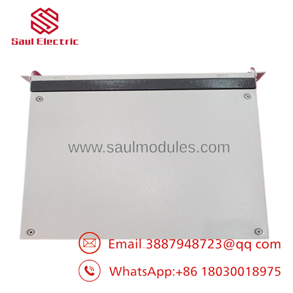
- AO2020
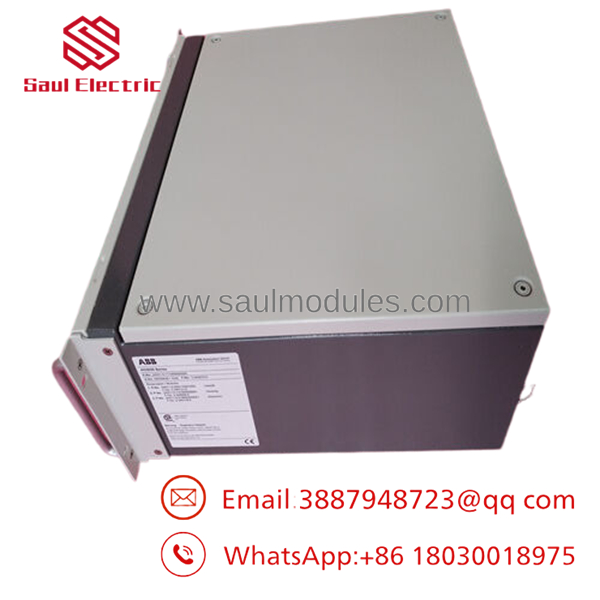
- AO2020
Installation & Configuration Guide
Stage 1: Pre-Installation Preparation (Estimated Time: 20 minutes)
- ⚠️ Safety First: Gas extraction lines can carry toxic, corrosive, or high-pressure sample compositions. Isolate the incoming physical gas manifold, purge the entire sample conditioning line with dry instrument air or nitrogen, and turn off the unit’s local AC mains circuit breaker.
- Tools Required: standard 19-inch rack screws, a PH2 Phillips screwdriver, wire terminal tools, and an active configuration laptop preloaded with ABB OptimaNetwork configuration software.
- Data Backup: If replacing an operating mainframe panel, use the front display interface keys to access the system setup menu. Export the component configuration tree, user security profiles, specific calibration coefficients, and Modbus device ID mappings onto an external data key or document them line by line.
Stage 2: Removing the Old Module (Estimated Time: 15 minutes)
- Verify that the incoming gas sample stream is isolated and fully depressurized.
- Unplug the primary AC power supply cord socket from the rear utility faceplate.
- Label and disconnect all network cables, discrete relay alarms, and analog 4-20 mA output wire blocks.
- If internal gas lines route through the unit casing, unscrew the compression Swagelok fittings carefully using backing wrenches. Seal the open sample tube stubs with clean plastic caps immediately.
- Remove the four 19-inch front mounting frame screws while supporting the unit weight from beneath, then slide the 4U chassis smoothly out of the rack assembly cabinet.
- ⚠️ Note: Continuous gas analyzers are precision optoelectronic structures; avoid hard physical drops or extreme vibrations during transport.
Stage 3: Installing the New Module (Estimated Time: 25 minutes)
- Ensure the empty rack slot is free of wiring obstructions and that adequate ventilation spacing exists above and below the 4U zone.
- Slide the new AO2020 mainframe unit onto the cabinet support angles and bolt it into the vertical rack strips using standard hardware.
- If shifting existing analyzer modules (such as a Uras photometer bench) into the new mainframe housing, slide them into the interior tracks carefully, ensuring the internal data bus ribbon plugs snap together securely.
- Reattach the gas sample lines to the rear inlet/outlet manifold stubs, tightening the compression nuts to specification using dual wrenches to prevent twisting the inner plumbing.
- Re-land the network communications links and discrete output signal terminal arrays.
Stage 4: Power-On & Testing (Estimated Time: 35 minutes)
- Energize the incoming AC utility mains circuit breaker.
- Observe the front display interface pane. The screen will illuminate and begin its software system kernel initialization sequence (typically booting database structures as shown on the LCD).
- Confirm that the green “Power” LED lights steadily, while the red “Error” LED drops off after the startup cycle finishes.
- Using the configuration software tool or front softkeys, populate the network parameters (IP address and mask) to re-establish lines to your CEMS tracking server.
- Run a formal zero-point calibration phase by flowing pure nitrogen gas through the system sample cell matrix, then check that the display concentration metrics settle to absolute zero without showing baseline drift errors.
- ⚠️ Troubleshooting Note: If the red “Error” LED flashes continuously after boot, access the diagnostic menu status log. The most common error stems from an internal module address conflict or a loose internal power harness connection after physical transit.
Frequently Asked Questions (FAQ)
Can I mix different analytical modules inside a single housing?
Yes, flexibility is the primary engineering intent behind the Advance Optima series architecture. A single unit can simultaneously manage an infrared photometer bench (Uras), a ultraviolet photometer cell (Limas), and a paramagnetic oxygen cell module (Magnos). The central processing board identifies each sub-module variant automatically upon backplane connection and populates the matching calibration menus on the front display interface.
Is the sample gas pumped directly by the mainframe card?
No, the chassis does not contain an internal sample gas transport pump. Continuous gas tracking configurations depend on an external sample conditioning rack system equipped with filters, coolers, condensation traps, and external sample pumps to deliver clean, dry, regulated gas into the rear analytical cells at the factory-specified flow limits.
Why does my display read a “Temperature Compensation Error” during initial power-on?
Optical photometer benches inside the device operate within highly regulated, insulated heated enclosures to eliminate drift caused by ambient temperature changes. When you first boot a cold unit, the internal heater elements require 30 to 60 minutes to bring the analytical benches up to steady-state operating target temperatures. The error flag will clear automatically once thermal equilibrium is reached.
How often should the automatic calibration routines be run?
While the non-dispersive infrared (NDIR) cells inside the modules are exceptionally stable, typical environmental regulations for CEMS mandate an automatic zero-point adjustment cycle every 24 hours (usually accomplished using ambient air or pure compressed nitrogen lines controlled by external solenoid valves). Full span-gas calibration checks are typically handled on a weekly or monthly maintenance schedule depending on local operating permits.
Can this unit be deployed directly outside next to a stack or flue?
No, the standard chassis holds an IP20 environment rating and is intended for climate-controlled analytical shelters, cabinets, or control rooms. Direct exposure to rain, high ambient humidity, or unmitigated solar loading will degrade the optoelectronic components, cloud the internal gas cell mirrors, and cause severe measurement drift. If field-level installation is required, the system must be installed inside a dedicated heated and air-conditioned NEMA-rated enclosure.

 Start Chat


