





Description
Key Technical Specifications
| Parameter | Value |
| Brand | ABB |
| Model Number | CI522A |
| Global Product ID | 3BSE018283R1 |
| Network Protocol | Advant Fieldbus 100 (AF100) |
| Transmission Rate | 1.5 Mbit/s |
| Topology Support | Twisted pair (via modems) or Coaxial bus segments |
| Connection Ports | 2 x 9-Pin D-Sub (Female) on front faceplate |
| Redundancy | Full dual-channel media redundancy supported |
| Host System Fit | Advant Controller 400 Series (AC410, AC450), APC panels |
| Net Weight | 0.38 kg |
| Country of Origin | Sweden (SE) |
Product Introduction
The ABB CI522A 3BSE018283R1 is a high-reliability communication interface board that integrates host automation systems into the proprietary Advant Fieldbus 100 (AF100) industrial network. Utilized extensively within the legacy Advant OCS architecture—specifically matching the Advant Controller 410 (AC410) and Advant Controller 450 (AC450) lines—this module ensures deterministic, high-speed cyclic data transmission at rates up to 1.5 Mbit/s.
Featuring full dual-channel network media support, the CI522A protects process control operations from physical line disruptions. The card’s front edge exposes twin 9-pin D-sub connectors designed to interface directly with external media attachment units or modems (such as the TC512 or TC513). This gives engineers the option to use either twisted-pair or coaxial network cabling topologies, depending on the plant’s layout.
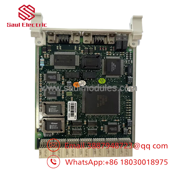
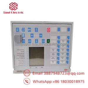
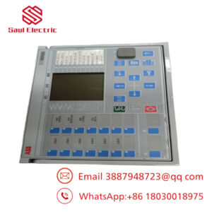
- CI522A 3BSE018283R1
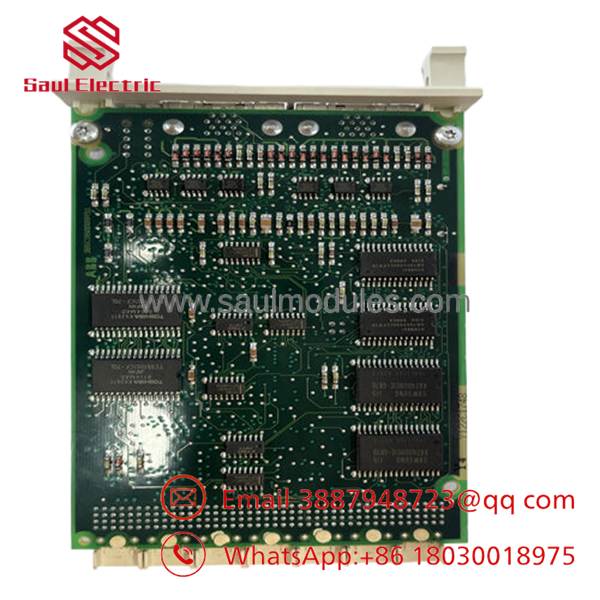
- CI522A 3BSE018283R1
Installation & Configuration Guide
1
Address Verification & Hardware Strapping
Estimated time: 5 mins
1.Address Verification & Hardware Strapping:Estimated time: 5 mins.
Set the module station address. Prior to slotting the card into the subrack, locate the hardware DIP switches or jumper blocks on the PCB surface. Configure the unique station binary address to match the exact node allocation defined in your AMPL/Advant Control Builder software layout.
Ensure that no two modules on the same local subrack segment share an identical backplane address identifier.
2
Subrack Insertion
Estimated time: 10 mins
2.Subrack Insertion:Estimated time: 10 mins.
Isolate the power supply to the destination subrack rack enclosure. Wear an ESD grounding wrist strap attached directly to the cabinet steel infrastructure.
Align the top and bottom edge card guides of the CI522A with the target slot rails in the subrack assembly. Gently slide the card straight backward until the high-density rear connectors make initial contact with the backplane. Firmly press the faceplate locking tabs inward to fully seat the board, then tighten the retaining screws.
3
Network Media Connection
Estimated time: 15 mins
3.Network Media Connection:Estimated time: 15 mins.
Attach your dual AF100 network drop lines to the front 9-pin D-sub interface connectors. Channel A must connect to your primary trunk infrastructure, and Channel B must map to the redundant backup path.
Ensure that the D-sub connector housing screws are turned down tight to ensure shielding continuity and prevent intermittent loss of signal in high-vibration control rooms.
Pre-Commissioning Checklist:
- [ ] Hardware node address matches the central system configuration map.
- [ ] Both Channel A and B connectors are completely locked.
- [ ] The card faceplate screws are grounded flush against the chassis frame.
4
Power-Up & Initialization diagnostics
Estimated time: 10 mins
4.Power-Up & Initialization diagnostics:Estimated time: 10 mins.
Restore auxiliary power to the controller subrack cluster. Monitor the board’s onboard LED array:
- Run/OK indicator: Should switch to steady green once the board completes internal boot tasks.
- Traffic/Link lights: Will pulse rapidly as cyclic communication frames begin synchronous execution over the AF100 network.
Log into the system management engineering console to confirm that the node status transitions to “Active/Healthy” with zero recorded frame cyclic errors.
Frequently Asked Questions (FAQ)
Q: What is the operational difference between the CI522 and the variant? A: The “A” suffix designates a hardware component revision optimized with updated silicon components to increase long-term thermal endurance and reduce electromagnetic emissions. The serves as a direct form-fit-functional drop-in replacement for older standard CI522 boards, requiring zero firmware conversion modifications or code changes in existing AC410/AC450 software setups.
Q: Can I run this module with only a single network cable connected? A: Yes, the card can function in non-redundant mode by utilizing Channel A alone. However, the host controller will generate an active system alarm warning of a missing redundant media link. For critical heavy industrial installations, running dual cable channels is highly recommended to protect against communication dropouts if a network cable is cut or damaged.
A: No additional drivers are necessary. The communication interface is natively recognized by the system firmware within the Advant OCS ecosystem (e.g., system software versions for AC450 or MasterPiece configurations). You simply need to define the matching slot address and node parameters within the hardware definition table of your control software project.
Q: What external modems are typically used to connect this card to twisted-pair cabling? A: The commonly interfaces with ABB’s TC512 or TC513 fieldbus modems. These modems convert the electrical signals from the card’s D-sub interface into a differential format optimized for long-distance transmission over rugged, shielded twisted-pair networks across the plant.

 Start Chat


