





Description
Key Technical Specifications
| Parameter | Value |
| Application Compatibility | ABB DCS800-S01 and DCS800-S02 (Units -0020-05 through -0140-05) |
| Rated Functional Current | Up to 140 A |
| Auxiliary Control Voltage | 24 V DC (+30%, −20%) |
| Maximum Control Current | 40 mA when internal fault relay is energized |
| Relay Switching Capacity | 12 to 250 V AC/DC; Max 1.5 A at 240 V AC (AC-15 rating) |
| Inductive Load Snubbing | Integrated free-wheeling diodes (DC) and varistors/VDRs (AC) |
| Visual Indicators | Green (Ready), Yellow (Diagnostic Warning), Red (Fault) |
| Mounting Base | Standard 35mm DIN-rail snap-on mounting |
| Protection Rating | IP20 / VBG4 enclosure standard |
| Physical Footprint | 22.5 mm x 77 mm x 100 mm (excluding external plug structures) |
| Temperature Range | 0 to +60 °C operational environment |
| Compliance Certifications | CE, cUL, ATEX, CCC, EAC |
Product Introduction
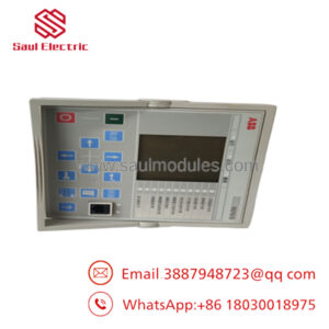
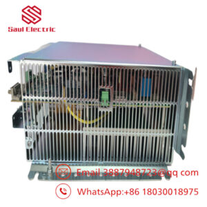
The ABB DCF506-0140-51 is a specialized active overvoltage protection unit designed to safeguard 3-phase field supply converters, specifically across DCS800-S01 and DCS800-S02 power architectures. Operating directly on the highly inductive loads typical of large DC motor fields, this module clamps and absorbs high-energy voltage spikes generated during sudden field-current interruption or supply commutation faults. By containing these unsafe voltage peaks, the module protects the thyristor stacks and control boards inside your main drive housing from critical voltage puncture failures.
Engineers specify the DCF506-0140-51 to prevent collateral damage and drive downtime on heavy-duty industrial cranes, extruders, and main mill drives. The module features integrated high-speed switching networks tied directly to a hardwired diagnostic relay, which communicates fault signals back to the master controller if a suppression element approaches thermal exhaustion. Its narrow, DIN-rail mountable footprint integrates into standard drive cabinets right alongside the auxiliary field power hardware without needing complex layout adjustments or independent external snubber enclosures.
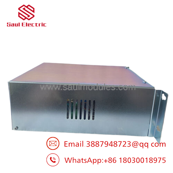
- DCF506-0140-51
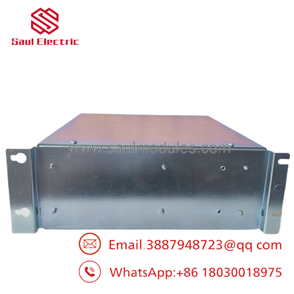
- DCF506-0140-51
Technical Pitfall & Survival Guide
- The Varistor Breakdown Blind Spot❗ Risk: High-energy spikes degrade the internal varistors over time. If they fail shorted, they can source raw AC power back into the 24 V DC control line or pop upstream circuit protection continuously.
- Avoidance: Never assume the module is bulletproof. Wire the integrated fault relay directly into your drive’s external fault or main contactor interlock loop. If the module’s protection layer degrades, it must drop the main line contactor immediately before a secondary spike punches through the field thyristors.
- Flyback Diode Installation Shunt Mismatch❗ Risk: Wiring field connections from memory without checking the specific polarity configuration of your current field supply converter. Reversing the DC terminals converts the protection network into a direct short circuit across the field output on power-up.
- Avoidance: Take a physical photo of the existing module terminals before pulling wires. I watched a technician drop a replacement card into a legacy cabinet on a Monday morning without verifying the layout. He powered the system up, and the unit immediately let out the magic smoke because he cross-wired the field excitation lines. Check the terminal designations every time.
- The Auxiliary Supply Float Trip❗ Risk: Powering the module using an unbuffered, shared 24 V DC rail that experiences voltage sags when massive line contactors fire. If the voltage drops below 19.2 V DC, the protective tracking circuit drops out, leaving the motor field completely unprotected during critical deceleration phases.
- Avoidance: Calculate your complete 24 V DC loop consumption. Ensure you maintain at least a 20% power overhead buffer, or feed the protection module from its own dedicated, isolated power supply drop.
Troubleshooting Quick Reference
| Symptom | Possible Cause | Relevance to this Part | Quick Check Method | Recommendation |
| Red “Fault” LED lit on faceplate | Protection component failure or internal varistor safety bridge open. | ✅ High | Check continuity across the onboard fault relay contacts. Verify if external field suppression fuses have opened. | The module has done its job and absorbed an unsafe voltage transient. It must be replaced to restore full drive protection. |
| Yellow “Diagnostic” LED flashing | Input excitation current exceeds safe thermal limits or voltage ripples are too high. | 🟡 Medium | Measure the field supply line current with a clamp meter. Compare values to the maximum 140 A threshold. | Reduce field current settings in your DCS800 drive parameters, or optimize field exciter tuning loops. |
| Green “Ready” LED dark while drive is live | Complete loss of auxiliary 24 V DC control supply or defective internal logic card. | ✅ High | Measure voltage directly across the designated 24 V DC auxiliary input terminals using a multimeter. | If 24 V DC is stable at the terminal pins but the Green LED is dead, internal power monitoring has failed. Swap out the module. |
| Upstream line fuses clear during field weakening | Shunted protection circuit or punch-through breakdown inside the field windings. | 🟡 Medium | Isolate the field connections completely. Run an insulation resistance test on the motor field using a 500V Megger. | If the field resistance reads high (less than 10MΩ), the motor winding is broken. If the motor tests clear, the DCF506 module is failed short. |
Frequently Asked Questions (FAQ)
Can I use the DCF506-0140-51 with a larger DCS800 drive unit rated for 200 A or higher?
No. The DCF506-0140-51 is strictly rated for applications up to 140 A. If you attempt to run this module on a larger drive—such as a 200 A or 5200 A unit—the current load will overheat the internal power paths, leading to rapid component breakdown. For those larger configurations, you must step up to the high-capacity DCF506-0520-51 module instead.
Is this module a universal surge protector, or will it only operate with ABB drives?
This is not a general-purpose surge protector. It is an active overvoltage clamping accessory specifically engineered to match the electrical characteristics and fault-handling logic of ABB’s -S01 and -S02 three-phase field supply converters. Using it with non-ABB exciter circuits can cause unexpected tripping points or failure to clamp spikes safely.
What is the difference between a DCF505 and a protection module?
The key difference is the underlying technology and drive generation support. The older DCF505 units are legacy modules designed for older drive architectures, whereas the series introduces updated active suppression component sizing, tighter tolerances, and full integration parameters optimized for modern series firmware architectures.
Does this specific part number include the protective plastic snap-on face cover?
To be completely clear, the base part number indicates an open-type chassis model that ships without an external plastic cover envelope. This style is designed for clean mounting directly inside an already enclosed, dust-free IP54 drive cabinet assembly where air circulation is crucial for passive cooling.
Why should I buy a New Surplus unit instead of waiting for a factory replacement order?
The primary driver here is lead time. Factory lead times for these specialized drive components can run several weeks or months. Our New Surplus units are physical, unused inventory sitting on shelves right now. They allow you to bypass supply-chain holdups and get an active backup or live replacement module into your facility by tomorrow morning.

 Start Chat


