





Description
Key Technical Specifications
| Parameter | Specification / Value |
| Number of Channels | 16 (configured as 2 groups of 8 channels) |
| Safety Certification | Certified up to SIL3 (IEC 61508) when used in redundant configurations |
| Output Voltage Range | Nominal 24 VDC (Accepts 19.2 to 30 VDC process supply) |
| Output Current Rating | 0.5 A maximum per channel (continuous) |
| Total Module Load Limit | 8 A maximum aggregate load |
| Overload / Short-Circuit Protection | Onboard electronic current limiting per channel (~1.5 A threshold) |
| Loop Supervision | Integrated open-circuit and short-circuit detection (in both ON and OFF states) |
| Leakage Current (OFF State) | <0.1 mA |
| Output Voltage Drop | <0.5 V at 0.5 A load |
| Redundancy Support | Built-in logic to support dual-module hot-standby redundancy |
| Modulebus Current Draw | 100 mA typical / 150 mA maximum @ +5 VDC |
| Power Dissipation | 4.5 W typical (excluding external field load currents) |
| Compatible MTUs | TU840, TU841, TU852 |
| Physical Dimensions | Width: 45 mm (1.77″), Depth: 102 mm (4.01″), Height: 119 mm (4.7″) |
Product Introduction
The ABB DO880 (3BSE028602R1) is a 16-channel, 24 VDC supervised digital output module designed for high-integrity and safety-critical applications within the S800 I/O system. Certified for use in safety-instrumented systems (SIS) up to SIL3, the DO880 provides current-sourcing outputs to drive solenoids, relays, indicators, and emergency shutdown devices.
Each of the 16 channels features advanced, continuous loop supervision capable of identifying open-circuit or short-circuit line faults in both the energized (ON) and de-energized (OFF) states without pulsing the load or causing false trips. Designed with hardware redundancy pathways, the DO880 can be deployed in pairs on a redundant Module Termination Unit (such as the TU840). This architecture is frequently utilized in functional safety circuits, emergency shutdown (ESD) loops, and burner management systems (BMS) managed by ABB AC 800M High-Integrity controllers.
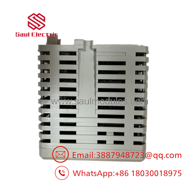
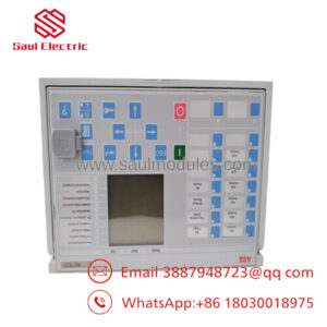
- DO880
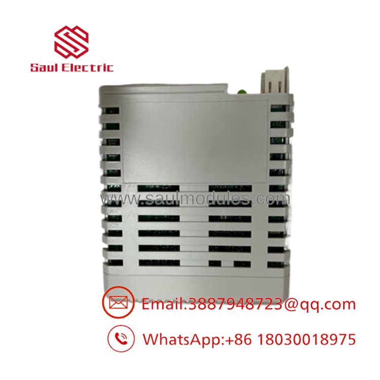
- DO880
Troubleshooting Quick Reference
| Symptom | Possible Cause | Relevance to this Part | Quick Check Method | Recommendation |
| Front panel F (Fault) LED is solid red | Internal watchdog failure, component hardware fault, or unsafe diagnostics state | ✅ High | Read diagnostic logs in ABB Control Builder. Perform a power cycle of the specific Modulebus node. | If the fault persists or points to internal ROM/RAM corruption, the internal processor core is damaged. Replace the module immediately. |
| Front panel W (Warning) LED is solid yellow | External loop anomaly (Open Circuit or Short Circuit) or process power missing | ✅ High | Measure the resistance of the external load circuit. Verify that the 24 VDC process supply is present on the MTU terminals. | If process power is good, check the physical field load wiring for a broken connection or shorted coil. Correcting the external loop fault clears the warning. |
| An active channel output drops down to ~0V despite software logic commanding “1” | Overload or short circuit has tripped the on-board electronic fuse | ✅ High | Disconnect the field load at the MTU and measure the resistance of the solenoid coil. Normal 0.5 A loads should be >48 Ω. | If the coil is shorted (<10 Ω), swap the solenoid. The DO880 automatically recovers and restores output voltage once the short is removed. |
| Mismatch in firmware versions or bad redundant MTU backplane connection | ✅ High | Check if both modules are running the exact same firmware build version. Ensure both are seated firmly in the TU840. | Align the firmware versions of both cards via the system software. Clean backplane connector sockets if dirty. |
Note: For complex safety-instrumented system (SIS) trip diagnostics, firmware revision locks, or detailed loop-monitoring threshold configurations, please capture your controller’s error log files and contact our technical support engineers.
Frequently Asked Questions (FAQ)
Q: Does the loop supervision on the cause fast-acting solenoids to flicker or chatter?
A: No. The uses highly advanced, ultra-short test pulses (under 1 millisecond) to check the integrity of the copper lines while the output is in both ON and OFF states. These diagnostic pulses are designed to check for open or short circuits but do not contain enough energy to overcome the physical inertia of mechanical solenoids, relays, or actuators. Your field devices will remain stable during active monitoring.
Q: Can I use the DO880 in non-safety (Standard) control applications, or is it strictly for SIL3 systems?
A: While the is built and certified for SIL3 safety loops, it is fully backward-compatible with standard, non-safety AC 800M system configurations. Many facility managers choose to install the in standard production lines because of its excellent diagnostics and loop-supervision features, which make identifying field wiring breaks or shorted solenoids incredibly simple without having to manually trace wires with a multimeter.
Q: What is required to run this module in a redundant, hot-standby configuration?
A: To set up hardware redundancy, you must use a redundant Module Termination Unit (MTU), such as the TU840 or TU841. You will need to plug two modules side-by-side into the MTU slots. The internal hardware logic on the cards coordinates active and hot-standby tasks, ensuring that if one card suffers an internal fault, control shifts to the secondary module without dropping the output voltage to the field.
Q: Why does the system trigger an “Open Loop” warning when driving very low-power indicator lights or micro-relays?
A: To be honest, this is a common physical limitation of safety I/O. The loop supervision on the is tuned to look for a minimum current draw to verify that a load is physically connected. If you connect an extremely low-power device (such as a high-efficiency LED indicator or a micro-relay drawing less than 2 mA), the cannot distinguish the device from a broken wire. To fix this, you must install an external shunt resistor (dummy load) in parallel with the device, or disable the open-loop supervision parameter for that specific channel in your software.
Q: What is your engineering protocol for testing these complex high-integrity modules before shipping?
A: Because the is used in life-safety and emergency shutdown loops, our testing protocol is highly strict. We mount the module onto an active redundant TU840 MTU within a live AC 800M test cluster. We run a rigorous script that exercises all 16 channels under a continuous 0.5 A load, inject real-time line faults (short-circuits and open-circuits) to verify that the internal diagnostic logic correctly flags the errors, and test the redundant transfer sequence between active and standby units. The module is only approved for ESD-safe sealing and shipping once all safety-relevant registers are confirmed to operate perfectly under thermal stress. Every order includes a signed copy of our test log.

 Start Chat


