





Description
Key Technical Specifications
| Parameter | Specification |
| Part Number | 57160001-KG |
| Module Type | Pulse Counter Board |
| System Compatibility | S100 I/O Rack for MasterPiece 200 / Advant Controller |
| Termination Interface | DSTX 120 Connection Unit (QGLF 108) |
| Typical Backplane Draw | 5 V DC, approx. 450 mA |
| Input Signal Types | Incremental pulse trains, square wave, encoder signals |
| Isolation | Optocoupler galvanic isolation between field loops and backplane |
| Dimensions | 234 mm x 22.5 mm x 324 mm |
| Net Weight | 0.39 kg |
| Country of Origin | Sweden |
Product Introduction
The ABB DSDP160 (part number 57160001-KG) is a dedicated high-speed pulse counter board designed for the legacy S100 I/O rack system. It provides precise frequency, speed, and positioning monitoring within MasterPiece 200 and Advant OCS architectures. By capturing and tallying rapid digital pulses directly at the hardware layer, it offloads high-frequency calculation strain from the central processor module, preserving execution bandwidth for core control loops.
This board interfaces directly with external instrumentation, including rotary encoders, turbine flow meters, and proximity pick-ups via a DSTX 120 connection unit. The onboard electronics integrate optocouplers that establish an electrical barrier between the field infrastructure and the internal logic bus, preventing field-side transients from damaging core backplane hardware. It remains an essential spare component for processing plants requiring zero-downtime maintenance of their existing legacy DCS infrastructure.
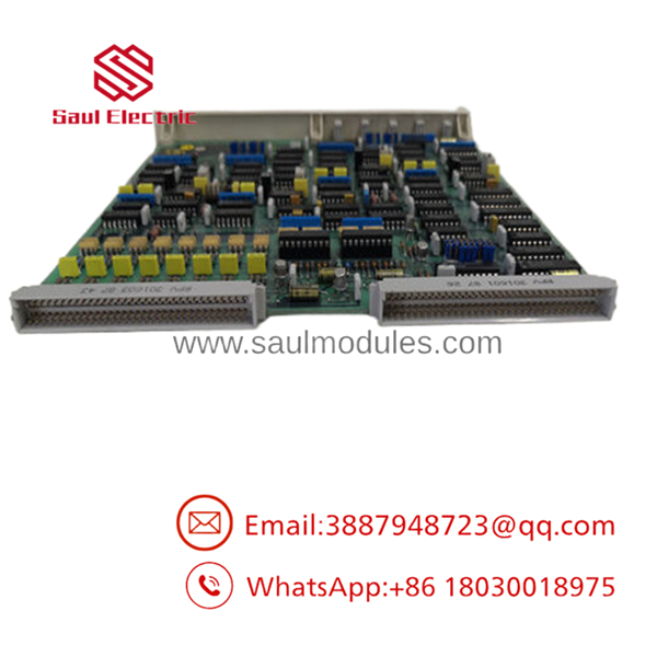
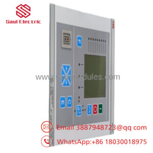
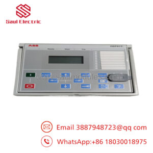
- DSDP160 57160001-KG
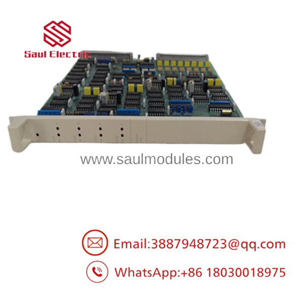
- DSDP160 57160001-KG
Troubleshooting Quick Reference
| Symptom | Possible Cause | Relevance to this Part | Quick Check Method | Recommendation |
| Counter values remain static while target shaft is rotating | Missing or degraded encoder input signals | ❌ Low | Connect an oscilloscope or high-frequency multimeter to the DSTX 120 terminal pins to verify incoming square waves. | Inspect the external encoder, sensor alignment, and field cabling integrity before replacing the card. |
| Hardware Fault LED illuminates or backplane drops card | Internal logic corruption or bus transceiver failure | ✅ High | Perform a cold rack restart. If the module fails to initialize its boot sequence and throws a solid red light, internal hardware is compromised. | Replace the DSDP160 board. |
| Count drift or missing pulses at high RPMs | Signal attenuation or incorrect threshold jumpers | ✅ High | Inspect the physical jumper configuration on the board to ensure it matches the electrical limits of your input sensor. | Reconfigure the onboard attenuation jumpers to match the sensor voltage peak. If problems persist under load, replace the board. |
| Intermittent data dropouts on the entire sub-rack | Backplane voltage dipping under high load | ❌ Low | Measure the 5 V DC supply rail directly at the rack power terminal block. | Confirm the power supply has at least a 20% overhead margin; check for a failing system power supply module. |
Frequently Asked Questions (FAQ)
Does the DSDP160 support hot-swapping during active operation?
No. The S100 I/O system backplane does not isolate data lines during live module extraction. Pulling this card while the sub-rack is powered can create voltage arcs that corrupt adjacent card communications or permanently damage the backplane bus. Always isolate the sub-rack power supply before pulling or inserting a card.
My original part number has a different letter suffix. Is the 57160001-KG directly compatible?
Yes, the 57160001-KG part number defines the standard physical board configuration for the DSDP160 series. Minor component variations over the years changed internal sub-component vendors, but the form factor, pinning to the DSTX 120 termination unit, and backplane command registers remain backward-compatible with your existing S100 configurations.
How do I adapt this pulse counter board for 5 V TTL vs. 24 V HTL encoder inputs?
Input signal conditioning is managed through onboard physical jumpers. This requires extracting the board and setting the jumper links according to the electrical specifications found in the original S100 I/O hardware manual. Failing to set these correctly will result in missing counts (if set too high for a 5 V signal) or overheating the input circuit (if feeding 24 V into a 5 V configuration).
What exactly is the purpose of the paired DSTX 120 unit listed in your specs?
The itself is a bare circuit card that slides directly into an S100 slot. It does not contain screw terminals for field cables. The DSTX 120 is the dedicated external terminal block (Module Termination Unit) that mounts on the cabinet DIN rail and routes field wiring via a ribbon cable directly into the rear connector of the rack slot.
Why choose New Surplus inventory over ordering a factory repair from the OEM?
Because this series is obsolete, factory lead times for repairs or certified legacy replacements often span weeks or months, inducing severe financial penalties during down-time. Our New Surplus inventory consists of unused, functional stock that can ship out immediately. Every unit is subjected to standard parameter checkouts and includes a full 1-year warranty.

 Start Chat


