





Description
Key Technical Specifications
| Parameter | Value |
| Model Designation | NGPS-12 / NGPS-12C |
| Product ID (Part Number) | 64361864 (also links to PCB layouts 857803 / 857804C) |
| Primary Input Voltage | 115 V AC / 230 V AC (\pm10% auxiliary line circuit) |
| Internal Operating Frequency | 50 kHz |
| Application Scope | Provides gate emitter/control supply for output stage inverter modules |
| Physical Dimensions | 152 mm (W) x 51 mm (D) x 203 mm (H) |
| Net Weight | 0.30 kg (0.66 lbs) |
| Shipping Weight | Approximately 2.0 kg (with industrial packaging) |
| Coating Protection | Conformal coated (specifically variant NGPS-12C / 857804C) |
| Country of Origin | Sweden |
Product Introduction
The ABB NGPS-12 (64361864) is a specialized internal power supply board engineered for legacy ACS600 MultiDrive and high-power inverter modules. Rather than serving as a general cabinet power supply, this board is mounted directly into the frequency converter infrastructure to supply the critical gating and control voltage required by the output stage’s semiconductor switches.
Operating at an internal switching frequency of 50 kHz, the NGPS-12 handles precise voltage step-down from the auxiliary 115/230 V AC line. The conformal coated version (NGPS-12C) prevents trace deterioration or failure modes driven by airborne particulates and humidity. Because this board directly dictates the gate drive state, maintaining a healthy, original board is essential for preventing catastrophic IGBT shorts in large motor applications.
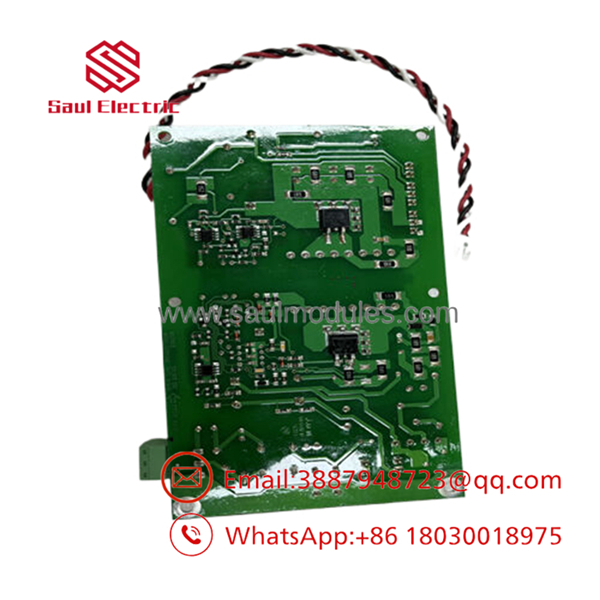
- NGPS-12
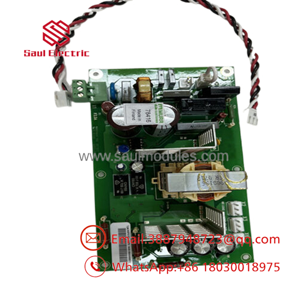
- NGPS-12
Installation & Configuration Guide
Stage 1: Pre-Installation Preparation
- Estimated Time: 15 minutes
- ⚠️ Safety First: Disconnect the main AC mains feed to the drive system. Isolate the external 115/230 V AC auxiliary power circuit that feeds the control boards. Lock out and tag out (LOTO) all energy sources. * Critical Wait Time: Internal intermediate circuit capacitors hold dangerous residual voltages. Wait at least 5 minutes after disconnecting power. Use a calibrated multimeter to verify that the DC bus voltage across terminals UDC+ and UDC- relative to the frame chassis is 0 V before touching any hardware.
- Tools Required: Grounded ESD wrist strap, PH1 and PH2 screwdrivers, insulated digital multimeter (DMM).
Stage 2: Removing the Old Module
- Estimated Time: 10 minutes
- Steps:
- Securely attach your ESD wrist strap to an unpainted grounded frame member.
- Map out, label, and safely unplug the incoming auxiliary power supply connector wires from the board terminals.
- Carefully disconnect the low-voltage output ribbon cables or jumpers leading to the inverter control stage/gate drivers. Do not pull on the cables directly; use the connector housings.
- Undo the retention screws holding the PCB card to the chassis bracket. Slide the board out cleanly, taking care not to scrape any surface components against neighboring frames.
Stage 3: Installing the New Module
- Estimated Time: 10 minutes
- Steps:
- Unbox the replacement NGPS-12 inside the static-safe zone. Verify that the hardware part codes (e.g., 857804C vs 857803) match the insulation and coating specs needed for your factory environment.
- Align the mounting holes of the board with the chassis standoffs. Fasten the retention screws securely, but do not over-torque to avoid cracking the PCB.
- Reattach the internal low-voltage gate distribution ribbon cables, making sure the keying alignment index snaps in flush.
- Reconnect the 115/230 V AC auxiliary feed lines exactly as labeled during removal.
- Self-Checklist:
- [ ] Standoff screws secured snugly
- [ ] Ribbon cables seated completely with latch clips engaged
- [ ] Line voltage wiring checked for correct terminal pinout
Stage 4: Power-On & Testing
- Estimated Time: 10 minutes
- Pre-Power Check: Double check that no loose washers, copper strands, or tools are left sitting on the power board traces.
- Power-On Steps:
- Energize the 230/115 V AC auxiliary power circuit only (keep the main high-voltage DC/AC motor bus offline).
- Verify that the gate driver card status lights illuminate correctly without triggering localized safety loop trip states.
- Measure the secondary outputs if test points are exposed, validating clean supply generation.
- Re-energize the main line voltage to the inverter intermediate stage, boot the local control panel, and monitor for diagnostic codes like “Under-voltage” or “Gate Driver Fault.”
- ⚠️ Troubleshooting Note: If the drive immediately triggers an auxiliary circuit fault or blocks firing pulses upon power up, verify the external safety switch loop. The line usually flows through a customer-installed normally-closed emergency block switch; if this switch is open, the module’s control voltage is cut off, halting the inverter power stage.
Frequently Asked Questions (FAQ)
Can I replace an with an NGPS-12C?
Yes. The NGPS-12C is the conformal-coated variant of the standard . The footprint, input values, and terminal connections match exactly. Upgrading to the “C” variant is highly recommended because it offers superior insulation resistance against conductive dust and humidity, which are typical causes of failure on the older, non-coated boards.
What happens if the loses power while the motor is running?
If the auxiliary supply feeding the is interrupted or drops below the voltage tolerance threshold, the board stops delivering gate voltage to the inverter power stage. This causes the firing pulses to block instantly. The drive will immediately throw a major fault and the motor will coast to a stop, preventing the uncontrolled switching states that could damage the power semiconductors.
Why is this board listed as obsolete, and can I still get reliable replacements?
The ACS600 series has passed out of active production lifecycle phases into the limited/obsolete support window. Consequently, these components are no longer manufactured by the factory. Available stock consists of original new surplus or certified refurbished units. Every board must undergo component-level inspection and static testing prior to installation to ensure reliability.
Does the board store parameter configurations or software versions?
No. The is an analog switching power supply board that handles raw voltage transformation for the gating electronics. It does not carry application programs, motor parameters, or digital firmware. You do not need to perform flash loading or parameter restoration when replacing this board.
Can I run the unit on 24 V DC instead of 115/230 V AC?
No. The is explicitly designed to tap into the high-voltage AC auxiliary power circuit (typically 115 V AC or 230 V AC) running through the drive cabinet enclosure. It cannot be powered from or interface with standard 24 V DC automation loops. Trying to feed low-voltage DC into the AC input will prevent the unit from initializing completely.


 Start Chat


