





Description
Key Technical Specifications
| Parameter | Value |
| Model Designation | PFEA113-65 |
| Product ID | 3BSE028144R0065 |
| Enclosure Rating | IP65 (NEMA 4X equivalent) for direct field wall mounting |
| Input Power Supply | 24 V DC (18 to 36 V DC working range, typical consumption 8 W) |
| Supported Load Cells | Up to two ABB PillowBlock, Radial, or Web Tension Load Cells (PFCL, PFRL, PFTL, PFTB) |
| Excitation Voltage | Constant current, square-wave excitation (typically 330 mA) |
| Analog Outputs | 2x Configurable Outputs: -10 to +10 V, 0 to 10 V, 4 to 20 mA, or 0 to 20 mA |
| Digital Fieldbus | PROFIBUS-DP (supports speeds up to 12 Mbps via standard 9-pin sub-D or terminal block) |
| Display/Interface | Integrated 2 x 16 character backlit LCD with 4-button tactile keypad |
| Operating Temperature | -10 to +55°C (14 to 131°F) |
| Weight | 3.5 kg (7.7 lbs) |
Product Introduction
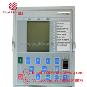
The ABB PFEA113-65 (3BSE028144R0065) is a high-precision, field-mount tension electronics controller designed to interface directly with ABB’s portfolio of web and strip tension load cells. Operating as a dedicated signal conditioning and calculation hub, the PFEA113-65 processes micro-volt level differential signals from up to two load cells, calculating real-time total, right, or left web tension values in paper mills, steel rolling lines, and converting machinery.
Unlike the DIN-rail version (PFEA111), the PFEA113-65 is housed in a heavy-duty IP65 industrial enclosure, allowing direct field mounting adjacent to the physical process without additional protective cabinets. Equipped with an onboard PROFIBUS-DP fieldbus interface, dual analog outputs, and programmable digital I/O, it bridges physical web-handling mechanics with primary PLC/DCS controllers such as ABB’s AC 800M or Rockwell’s ControlLogix.
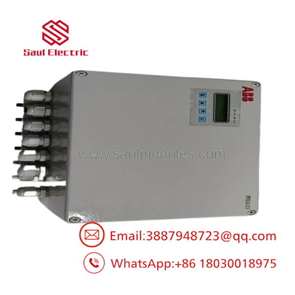
- PFEA113-65 3BSE028144R0065
Installation & Configuration Guide
Stage 1: Pre-Installation Preparation
- Estimated Time: 15 minutes
- ⚠️ Safety First: Ensure the power supply to the auxiliary 24 V DC lines is switched off, locked out, and tagged out. Verify that the web processing line is completely stationary to prevent unexpected movement of tension rollers during sensor connection.
- Tools Required: Grounded ESD wrist strap, flathead screwdriver (for terminal clamps), metric Allen keys (for the IP65 enclosure cover), digital multimeter, and a micro-volt calibration source (optional, for field simulation).
- Data Backup: Document the current load cell calibration factors (expressed in mV/V or kN) and wrap angles for the mechanical roll layout.
Stage 2: Removing the Old Module
- Estimated Time: 10 minutes
- Steps:
- Wear your grounded anti-static wrist strap.
- Unscrew the cover of the IP65 enclosure.
- Disconnect the 24 V DC power terminal block.
- Unplug or unscrew the delicate, shielded load cell input cables from the terminals. Label the wires for Load Cell A and Load Cell B to prevent reverse calculation errors.
- Disconnect the analog outputs and PROFIBUS-DP lines.
- Loosen the four wall-mounting screws holding the enclosure body to the support frame, then lift the old unit clear.
Stage 3: Installing the New Module
- Estimated Time: 20 minutes
- Steps:
- Mount the new IP65 PFEA113-65 enclosure to the wall or mechanical frame using four M6 mounting screws. Ensure the cable glands point straight down to prevent moisture entry.
- Thread all cables through the appropriate glands, ensuring the shielding on the load cell cables is correctly grounded at the metal gland entry point.
- Wire the load cells to terminals X1 and X2 on the board. Maintain the shield continuity as close to the terminal blocks as possible.
- Connect the 24 V DC power wires to the terminal strip.
- Securely wire the PROFIBUS-DP network cable or the analog output control loop.
- Self-Checklist:
- [ ] Enclosure mounted with cable glands pointing downward to block condensation
- [ ] Load cell cable shields properly terminated inside the grounding clamps
- [ ] All unused cable gland entries sealed with tight plugs
Stage 4: Power-On & Testing
- Estimated Time: 15 minutes
- Pre-Power Check: Ensure there is no physical weight or web material draped over the tension measuring roll. The load cells must be under a “zero load” state.
- Power-On Steps:
- Apply 24 V DC control power.
- Observe the LCD display. The will execute an internal diagnostics check and enter the main monitoring display.
- Navigate the keypad to the Service Menu to enter the commissioning parameters:
- Load Cell Type: Match the connected sensors (e.g., PFCL 201).
- Calibration Method: Select “Standard Calibration” or “Hang-Weight Calibration.”
- Zero Set: Execute the zeroing procedure with the roll completely empty.
- Nominal Force / Gain: Enter the factory calibration certificate values for the load cells.
- Perform a test by hand-pressing the roller down. Verify that the tension value increases linearly in the correct positive direction on the LCD and within your PLC diagnostic tags.
- ⚠️ Troubleshooting Note: If the display shows “Overload” or “Sensor Fault,” use your multimeter to check the resistance across the load cell excitation pins. If you read an open circuit, check for physical terminal wire fractures inside the cable glands.
Frequently Asked Questions (FAQ)
Can I hot-swap the while the web tension line is running?
No. While the PROFIBUS network might recover from a drop, disconnecting the tension electronics while the web is under active PID control will cause the drive or PLC to lose its feedback signal. This typically causes the winders to either free-spin or lock up, likely breaking the web material or damaging the machine. Always put the drive line into manual or safe-stop mode before servicing.
Why is the shield termination on the load cell cable so critical for this module?
Because the electrical signals generated by tension load cells are incredibly small (often measuring in the millivolt/micro-volt range), high-frequency electromagnetic noise from neighboring VFD drive cables can easily distort the readings. If the cable shields are not correctly bonded to the ground rail at the entry glands, you will see highly unstable tension readings, causing the drive’s tension loop to hunt or oscillate.
How do I address the on a PROFIBUS-DP network?
Unlike older hardware that relies on physical rotary dials, the node address of the is configured electronically through the front-panel LCD and keypad interface. Navigate to the Fieldbus Menu, set your target PROFIBUS node address, and restart the unit to lock the address into the module’s non-volatile memory.
Can this controller support two load cells of different nominal loads simultaneously?
No. The is designed to calculate composite tension based on a balanced roll configuration. Both connected load cells must be of the same model, series, and nominal load rating. Mixing load cell models on terminals X1 and X2 will result in unbalanced calculation profiles and highly inaccurate process values.
What calibration method is recommended if I cannot hang weights from the roller?
If mechanical constraints prevent you from performing a hang-weight calibration (the most accurate method), you can use the controller’s built-in Standard Calibration mode. This method calculates tension mathematically by utilizing the factory load cell parameters (mV/V sensitivity rating printed on the sensor’s nameplate) combined with the physical wrap angle parameters entered via the keypad.

 Start Chat


