





Description
Key Technical Specifications
| Parameter | Specification / Value |
| Model Number | REF615 HBFEAEAGABB1BNA11E |
| Product Series | Relion 615 / Feeder Protection |
| Standard Configuration Code | B (Directional overcurrent and earth-fault protection) |
| Analog Inputs | 4 Current Transformers (CT) + 4 Voltage Transformers (VT) |
| Binary Inputs / Outputs | 8 Binary Inputs (BI) + 10 Binary Outputs (BO) |
| Auxiliary Power Supply (U_{aux}) | 100–240 V AC (50/60 Hz) / 110–250 V DC |
| Communication Hardware | Ethernet 100Base-TX (RJ45 port) + RS-485 serial |
| Communication Protocols | IEC 61850, Modbus TCP/RTU, DNP3, IEC 60870-5-103 |
| Rated Frequency (f_n) | 50 Hz / 60 Hz (user-configurable) |
| Enclosure Protection Class | IP54 (front panel, flush mounted), IP20 (rear terminals) |
| Operating Temperature | −25 °C to +55 °C |
| Physical Dimensions (W x H x D) | 177 mm x 177 mm x 201 mm |
| Net Weight | 4.10 kg (9.04 lbs) |
Product Introduction
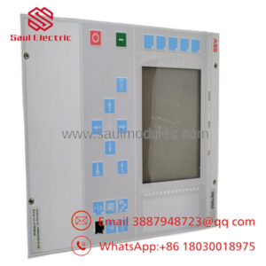
The ABB REF615 HBFEAEAGABB1BNA11E is a numerical feeder protection relay designed for liquid-insulated or gas-insulated switchgear installations in utility substations and industrial power systems. Configured with standard Configuration B, this unit delivers precise directional and non-directional overcurrent and earth-fault protection, complemented by comprehensive voltage, frequency, and three-phase power measurement capabilities.
This model is equipped with a hardware configuration featuring 4 CT and 4 VT analog measurement channels alongside 8 binary inputs and 10 binary outputs. It supports native high-speed horizontal communication via IEC 61850 GOOSE messaging, making it highly suitable for substation interlocking schemes, load shedding, and busbar protection applications where millisecond-level response times are mandatory.
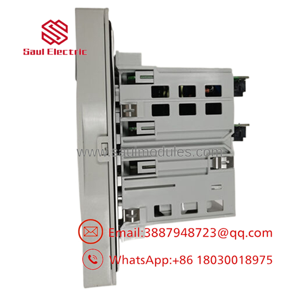
- REF615 HBFEAEAGABB1BNA11E
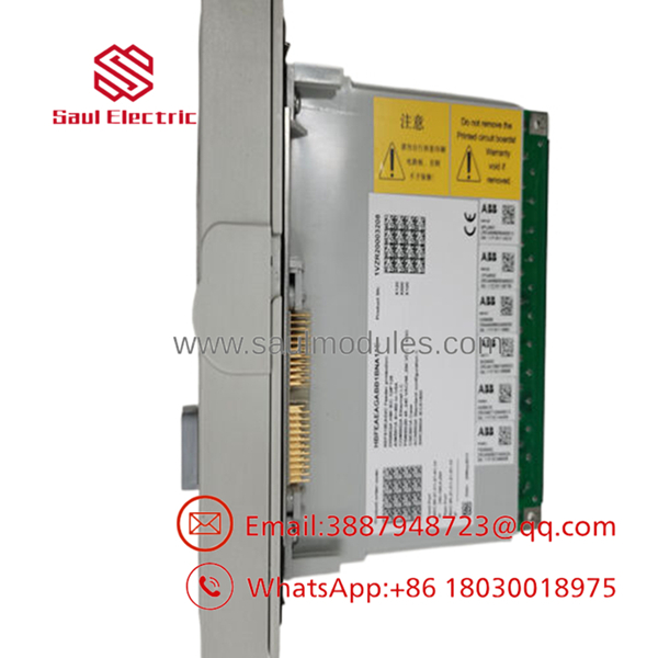
- REF615 HBFEAEAGABB1BNA11E
Installation & Configuration Guide
Replacing an older or failed Relion 615 relay requires strict adherence to safety and calibration steps.
Stage 1: Pre-Installation Preparation (Est. Time: 15 minutes)
- ⚠️ Safety First: Lock out and tag out (LOTO) all primary breakers associated with the feeder. Ensure the substation environment is dry.
- Tools Required: Grounded ESD wrist strap, small flat-head screwdriver, TX20 Torx driver, digital multimeter, and a laptop with ABB PCM600 software installed.
- Data Backup: Connect your PC to the active relay’s front RJ45 port and export the parameter settings file (
.pcmscdor.pcmpformat) using PCM600.
Stage 2: Removing the Old Module (Est. Time: 10 minutes)
- Attach your grounded ESD wrist strap to the panel frame.
- ⚠️ Danger: Never open-circuit an active current transformer. Verify that all CT secondary circuits are securely short-circuited at the test switch block before proceeding.
- Unplug the compression-type terminal blocks from the rear of the unit. Do not pull on the physical wiring bundles.
- Unscrew the four mounting collar fasteners holding the relay casing in the panel cutout and slide the chassis out.
Stage 3: Installing the New Module (Est. Time: 10 minutes)
- Slide the new REF615 HBFEAEAGABB1BNA11E into the cut-out slot.
- Tighten the collar screws to a torque rating of 1.5 Nm to ensure an IP54 seal against the panel face.
- Plug the rear terminal blocks back into their corresponding headers. The keyed terminals prevent incorrect insertion.
- Ensure the dedicated protective earth screw on the rear panel is connected to the main ground busbar using a copper wire with a cross-section of at least 4.0 mm^2.
Self-Checklist:
- [ ] Protective earth grounding wire secured
- [ ] Rear terminal blocks locked into place
- [ ] CT shorting links removed only after confirming the relay terminal connections are tight
- [ ] Front panel gasket is seated flush with the panel face
Stage 4: Power-On & Testing (Est. Time: 15 minutes)
- Apply auxiliary power (100–240 V AC or 110–250 V DC).
- The green Ready LED on the front panel must illuminate. A solid red Fail LED indicates a critical internal self-test error.
- Connect your laptop to the front RJ45 port using a standard Ethernet cable.
- Open PCM600, establish communication, and write the saved configuration file to the new relay.
- Verify that current and voltage scaling factors (CT/VT ratios) match your specific system drawing sheets.
Frequently Asked Questions (FAQ)
What is the purpose of the “B” in the HBFEAEAGABB1BNA11E code?
The second character of the configuration string (“B”) designates the pre-defined standard application configuration package. Configuration B offers directional overcurrent and directional earth-fault protection, plus voltage, frequency, and active/reactive power measurements. This contrasts with Configuration A, which only provides non-directional overcurrent protection.
Can this relay be pulled out of its case while the system is energized?
Yes, the Relion 615 series features a draw-out design. The plug-in unit can be withdrawn from the outer casing. When the plug-in unit is pulled out, the integrated CT connectors in the outer case automatically short-circuit to prevent high-voltage build-up across the open CT secondaries. However, for maximum safety, manual shorting at the test switch is still recommended before extraction.
Does this unit support IEC 61850 Edition 2?
Yes. The product version indicated by the configuration code “B” in the eleventh slot supports both IEC 61850 Edition 1 and Edition 2. This selection is configurable using ABB PCM600 software during the parameter setup stage.
Why does my relay show a “Phase Angle Error” after initial commission?
This error typically points to a phase sequence mismatch or reversed polarity on one of the CT or VT terminals. Check the analog measurement page on the local HMI to verify that the phase voltages and currents align with the expected phase rotation (usually L1-L2-L3). If one phase is shifted by 180°, double-check the physical wiring on the rear terminals.
What is the default IP address of the front communication port?
The default factory IP address for the front communication port of the REF615 relay is 192.168.0.254. Ensure your computer’s network adapter is set to the same subnet (e.g., IP: 192.168.0.100, Subnet Mask: 255.255.255.0) to establish a connection using PCM600.


 Start Chat


