





Description
Key Technical Specifications
| Parameter | Specification / Value |
| Model Number | REF615C_C |
| Complete Order Code | HCFFAEAGANB2BAN1XC |
| Standard Configuration | C (Line differential protection with directional overcurrent) |
| Analog Inputs | 4 Current Transformers (CT) + 4 Voltage Transformers (VT) |
| Binary Inputs / Outputs | 8 Binary Inputs (BI) + 10 Binary Outputs (BO) |
| Auxiliary Power Supply (U_{aux}) | 24–60 V DC (Low-voltage auxiliary variant) |
| Communication Interface | Ethernet 100Base-TX (RJ45) + RS-485 serial module |
| Protocol Support | IEC 61850, Modbus TCP/RTU, DNP3, IEC 60870-5-103 |
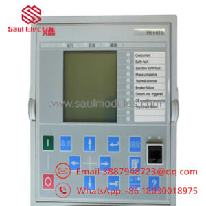
| Front HMI Display | Large LCD with programmable Bay Mimic diagram |
| Nominal Frequency (f_n) | 50 Hz / 60 Hz (software selectable) |
| Operating Temperature | −25 °C to +55 °C |
| Physical Dimensions (W x H x D) | 177 mm x 177 mm x 201 mm |
| Net Weight | 4.10 kg (9.04 lbs) |
Product Introduction
The ABB REF615C_C (HCFFAEAGANB2BAN1XC) is a high-performance numerical feeder protection relay within the Relion 615 family, specifically utilizing Standard Configuration C. This specific variant is optimized for closed-loop and radial medium-voltage utility networks where line differential protection (87L) is paired with directional overcurrent safeguards.
The “C” hardware configuration combines 4 current transformer (CT) inputs and 4 voltage transformer (VT) inputs to monitor power quality, active/reactive power flow, and vector shifts. Crucially, the HCFFAEAGANB2BAN1XC model is equipped with a low-voltage auxiliary power supply card rated for 24–60 V DC, making it the correct hardware choice for battery-backed substation control systems, telecom-grade control networks, or heavy industrial DC distribution panels.

- REF615C_C HCFFAEAGANB2BAN1XC
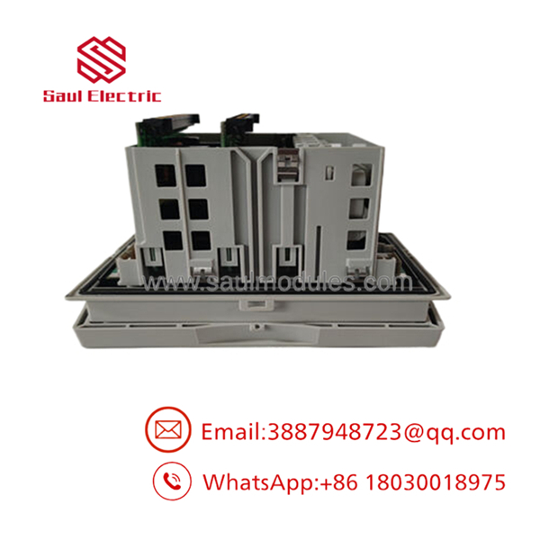
- REF615C_C HCFFAEAGANB2BAN1XC
Installation & Configuration Guide
Replacing an active protective relay demands precision to avoid accidental trips or damage to secondary instrumentation.
Stage 1: Pre-Installation Preparation (Est. Time: 15 minutes)
- ⚠️ Safety First: Contact the control room and flag the feeder for offline maintenance. Ensure the target breaker is racked out to the “Test” or “Disconnected” position. Lock out and tag out the breaker control circuits.
- Tools Required: Grounded ESD wrist strap, small flat-head terminal screwdriver, Torx TX20 screwdriver, digital multimeter, and a PC with ABB PCM600 software.
- Data Backup: Connect your PC to the front RJ45 port of the existing unit. Export the complete configuration file (
.pcmpor.pcmscd) to preserve custom logic mappings, user parameters, and event-log templates.
Stage 2: Removing the Old Module (Est. Time: 10 minutes)
- Clamp your grounded ESD wrist strap to a verified bare-metal ground point on the cabinet frame.
- ⚠️ Danger: Never open-circuit the secondary windings of an active CT. Verify that the external CT circuits are shorted using shorting links at your panel’s test switch block before proceeding.
- Unplug the terminal blocks on the rear panel. These blocks feature self-locking tabs; pull the connector bodies directly back, avoiding strain on the wires.
- Unscrew the mounting collar screws and slide the relay out of its panel cutout.
Stage 3: Installing the New Module (Est. Time: 10 minutes)
- Slide the new REF615C_C into the panel cutout.
- Tighten the collar screws to 1.5 Nm to seal the front gasket against dust and moisture.
- Secure the ground connection at the rear earth terminal using a low-impedance copper wire (minimum 4.0 mm^2).
- Insert all labeled terminal blocks into their respective slots. The blocks are mechanically keyed to prevent incorrect mounting.
Self-Checklist:
- [ ] Chassis ground screw torque verified
- [ ] All terminal blocks fully seated and locked
- [ ] External CT shorting links kept closed until wiring checks are completed
- [ ] Input power voltage verified to match the 24–60 V DC rating
Stage 4: Power-On & Configuration Load (Est. Time: 15 minutes)
- Apply control power (24–60 V DC).
- Wait for the self-test boot sequence. The green Ready LED on the HMI panel should illuminate steady.
- Connect your laptop to the front RJ45 port.
- Use PCM600 to upload the saved configuration backup into the new relay.
- Once configured, open your external CT shorting links, check the real-time current measurements on the HMI screen, and verify they match actual load currents before placing the feeder back in service.
Frequently Asked Questions (FAQ)
What voltage range does the HCFFAEAGANB2BAN1XC auxiliary card support?
This specific model code features the low-voltage power supply option, which accepts an input range of 24 to 60 V DC. It will not operate on standard 110–240 V AC/DC station batteries or mains power, and applying high voltage to these terminals will immediately damage the internal power card.
Can I load a backup file from a REF615 running Configuration B onto this Configuration C model?
No. The internal database structure and hardwired functional blocks of Configuration C (line differential optimized) differ from Configuration B (directional overcurrent optimized). If you attempt to write a Configuration B database into a Configuration C relay, PCM600 will flag an application incompatibility error and reject the write command.
How does the line differential (87L) function communicate with the remote end of the line?
The line differential protection requires a continuous, low-latency communication link to synchronize current vector measurements with the relay at the opposite end of the cable. This is typically achieved via a plug-in fiber-optic communication module installed on the rear of the unit, communicating over a dedicated dark-fiber run or an engineered multiplexed WAN network.
What is the purpose of the “X” in the final position of the ordering code?
The “X” suffix in the final slot of the ordering code indicates a special or customized hardware revision parameter (typically involving packaging specifications, a non-standard label language, or a specific conformal coating variant). The core protection, I/O, and communication features remain fully compatible with standard replacement units.
Can I use a standard patch cable to connect to the front RJ45 port?
Yes. The front RJ45 service port on the Relion 615 series features auto-MDI/MDI-X detection. You can connect using a standard straight-through Cat5e/Cat6 patch cable or a crossover cable directly to your engineering laptop.

 Start Chat


