





Description
Key Technical Specifications
| Parameter | Value |
| Manufacturer | ABB |
| Part Number (Model) | UBC717BE101 |
| Catalog Number (PNC) | 3BHE021887R0101 |
| System Platform | UNITROL 6000, AC 800PEC |
| Input Voltage | 24 VDC nominal (internal system backplane distribution) |
| Power Consumption | Approximately 20 W typical operational draw |
| Processor Architecture | Combined RISC processor and high-density FPGA array |
| Communication Links | High-speed dedicated fiber-optic channels, Ethernet control bus |
| Operating Temperature | 0 to +55 °C |
| Storage Temperature | −40 to +70 °C |
| Relative Humidity | 5% to 95% non-condensing |
| Weight | 1.10 kg (unboxed module weight) |
| Form Factor | Proprietary AC 800PEC rack-mount processor card |
Product Introduction
The ABB UBC717BE101 3BHE021887R0101 is an industrial-grade, high-speed processing and control board designed exclusively for ABB’s UNITROL 6000 excitation systems and advanced AC 800PEC high-power electronics controllers. Engineered to manage the ultra-fast loop control algorithms required by massive synchronous machines, this board coordinates thyristor bridge firing angles, monitors real-time field voltage and current metrics, and maintains stable generator synchronization with the power grid under dynamic and transient fault conditions.
This processor platform is chosen by utility engineers because it bridges standard plant-level automation networks with the sub-millisecond control environment needed for generator excitation. By embedding a dedicated real-time operating system alongside high-density hardware logic arrays, the board handles intense computational demands while resisting high electromagnetic interference (EMI) typical of turbine-generator halls, avoiding spurious trips and minimizing unprogrammed plant downtime.
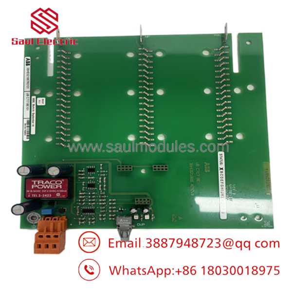
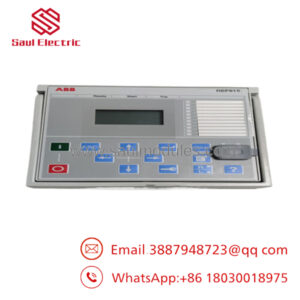
- UBC717BE101 3BHE021887R0101
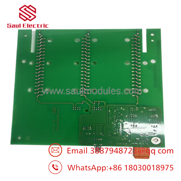
- UBC717BE101 3BHE021887R0101
Installation & Configuration Guide
Stage 1: Pre-Installation Preparation (Estimated Time: 15 Minutes)
- ⚠️ Safety First: Excitation systems handle dangerous voltage levels and immense stored energy. Coordinate with your dispatch desk to confirm target generator outage windows. Lock out and tag out (LOTO) the auxiliary 24 VDC control power lines and the high-voltage AC inputs feeding the thyristor bridge transformer. Wait a full 10 minutes to allow the field suppression circuits and capacitor banks to discharge completely. Verify a zero-energy state with a certified digital multimeter.
- Tools Required: Grounded electrostatic discharge (ESD) wrist strap, PH1/PH2 screwdrivers, clean fiber-optic inspection scope, optical click-cleaner, laptop loaded with ABB Control Builder / engineering package.
- Data Backup: Connect your service laptop to the existing controller. Execute an full upload of all system tuning coefficients, application firmware revisions, network settings, and localized Modbus/Profibus fieldbus station IDs. Capture photos of the board physical jumper locations for post-swap verification.
Stage 2: Removing the Old Module (Estimated Time: 10 Minutes)
- Clamp your ESD wrist strap to a verified, bare metal grounding post inside the cabinet enclosure.
- Carefully unplug the low-voltage auxiliary power and grounding terminals from the board front faceplate.
- Unclip and label all fiber-optic lines. Observe minimum bend radius limits (>30 mm) to protect internal glass cores. Immediately seal the cable ends and card optical ports with protective dust plugs.
- Unscrew the top and bottom retaining screws securing the board to the subrack.
- Apply equal pressure to the upper and lower plastic ejector tabs to release the unit from the internal backplane, then guide the board straight out along its alignment rails.
- ⚠️ Note: Keep this removed module nearby on an anti-static mat to directly cross-verify hardware component revisions and physical configuration blocks.
Stage 3: Installing the New Module (Estimated Time: 15 Minutes)
- Open the anti-static packaging while maintaining continuous grounding through your ESD strap.
- Configuration Clone (Crucial): Inspect the physical layout of the new UBC717BE101. Match all physical jumpers, sub-modules, and hardware setting switches exactly to the positions found on the original pulled unit. Incorrectly set switches can lead to hardware initialization loops or cause system bus lockouts.
- Slide the cleaned board smoothly into the designated subrack slot, pushing gently until the rear high-density pins latch fully with the backplane connector.
- Push down on the ejector handles to secure the module into position, and tighten the retaining screws to establish solid chassis ground continuity.
- Use the fiber click-cleaner on the optical cable ends, remove the dust caps, and reinstall the cables into their designated TX/RX ports.
- Self-Checklist:
- [ ] Physical jumpers/switches exactly match the decommissioned board configuration.
- [ ] Module is fully seated inside the rack with all structural screws tightened.
- [ ] Optical fibers are cleaned, clicked into correct ports, and run without tight crimps.
Stage 4: Power-On & Testing (Estimated Time: 20 Minutes)
- Pre-Power Check: Test for continuity across the board’s power inputs to ensure there are no short circuits relative to the frame.
- Power-On Steps:
- Switch on the local 24 VDC control power distribution breaker only (leave the main field power line disconnected).
- Monitor the startup sequence LED arrays on the faceplate. The unit should clear its self-test within 30 seconds. A solid green status indicates standard execution, while a blinking amber or red indicator points to a boot fault or missing communication link.
- Connect your laptop to the diagnostic port. Query the hardware status to verify the board’s active firmware version. If the new card contains an alternative firmware baseline, re-flash it to match the exact version saved during your site backup stage.
- Re-load the archived site application logic and control coefficients to the non-volatile memory block.
- Perform an I/O and communication loop test, verifying functional signal paths to downstream firing pulses and upstream DCS nodes prior to restarting the machine.
- ⚠️ Troubleshooting Note: If the master rack signals a “Module Missing” error after boot, power down the rack and inspect the rear pins for any alignment damage, or double-check that the board’s address jumpers are set accurately.
Frequently Asked Questions (FAQ)
Can this UBC717BE101 card be hot-swapped while the turbine is online?
No, hot-swapping is not supported. Removing this module breaks the main control loop for the synchronous machine’s excitation cycle. Doing so will freeze firing pulse updates to the power semiconductors, causing an immediate field collapse, a master system trip, and possible machine damage due to sudden reactive power shifts. Always bring the generator to a complete stop and ensure a zero-energy state before replacement.
Is this an authentic, factory-original component?
Yes. Our inventory represents New Original / New Surplus assets sourced directly from plant construction cancellations, spare parts reserves, or strategic inventory drawdowns. These boards are unused, ship in their original industrial packaging configurations, and have been preserved in clean, temperature-regulated facilities to ensure component longevity.
What should I do if the new board’s firmware does not match my existing system?
If you encounter a firmware version conflict, the master AC 800PEC controller will prevent the card from participating in the active control task. You must connect your engineering workspace tools during the initial 24 VDC power-up phase to verify the software revision. If needed, flash your plant’s archived application image directly to the new module to bring it into alignment.
Why is your pricing lower than purchasing directly from standard OEM factory channels?
We specialize in provisioning industrial overstock, surplus project allocations, and liquidated enterprise parts inventories. By acquiring these authentic assets outside traditional factory distribution networks, we can reduce asset costs significantly and extend those savings to your operational maintenance budgets.
What form of warranty backup is included with this control module?
Each module includes a comprehensive 1-year replacement warranty starting from your delivery date. If the hardware exhibits any operational faults or component failures under normal operating conditions within this timeframe, we will provide an immediate replacement module or process a full refund if replacement stock is unavailable.
Core Strategy 1: SOP Quality Transparency
To ensure maximum uptime and mitigate the risks associated with sourcing legacy components, all incoming processor cards pass through our multi-phase quality verification cycle:
- Inbound Inspection & Traceability:
- Documentation traces are checked against commercial shipping registers and original corporate procurement records.
- Visual examinations under magnification confirm pristine PCB solder pads, intact factory silkscreening, and authentic serial label prints.
- Accessorie checks are conducted to verify that all necessary terminal blocks or shielding plates remain present.
- Electrical Parameter Testing:
- Insulation resistance profiling is executed with a Fluke 1507 insulation tester at 500 VDC across internal power buses to ensure resistance values exceed 10 MΩ.
- Grounding continuity mapping confirms that the card’s low-impedance protection pathways are fully continuous to prevent floating noise issues in the field.
- Live Functional Testing:
- The module is inserted into an authentic ABB AC 800PEC development rack powered by an isolated, regulated 24 VDC power supply.
- A full hardware power-on self-test (POST) verifies standard processor boot phases and led initialization behavior.
- High-speed fiber-optic links are coupled to network loopback fixtures to confirm that data transmission rates match exact performance parameters with zero signal dropouts.
- Modules are subjected to a continuous 24-hour burn-in period while thermal imaging cameras screen for localized component overheating or voltage drops.
- A customized QC Test Record is archived for your machine records; verification videos can be provided on request before shipping.
- Firmware & Configuration Verification:
- The resident firmware core is extracted, logged, and confirmed stable.
- Physical jumper sets are inspected and reset to factory defaults, ensuring an uncomplicated setup baseline for your field engineers.
- Final QC & Packaging Control:
- The supervising inspector confirms quality criteria compliance and signs off on the final tracking sheet.
- The board is encased inside an airtight, moisture-resistant anti-static (ESD) protective sleeve.
- It is packed using high-density bubble wrap inside custom, multi-wall corrugated cardboard shipping boxes to prevent shock damage during transit.
- The outer container is sealed with a dated “QC Passed” label.
Core Strategy 2: Technical Pitfall & Survival Guide
Replacing high-speed control cards in critical power electronics requires absolute precision. Avoid these 5 frequent installation mistakes:
- ❗ Firmware Discrepancy Failure:
- The Trap: Installing a replacement card with an alternative or newer firmware baseline often locks out communication with your legacy system architecture, resulting in a general initialization fault during boot.
- Survival Strategy: Always check and note down your operational firmware version prior to extracting the failed board. Never assume that the replacement unit is running the identical software version; use your engineering software to read out and cross-reference versions before applying live control logic.
- ❗ Mismatched Board Jumpers:
- The Trap: Replacement modules are normally configured with standard factory defaults. If your plant application relies on modified jumper addressing or custom network terminator settings, a direct swap without adjustment will cause system bus errors.
- Survival Strategy: Treat this as a vital step. Use your phone to snap a high-resolution photograph of the failed board’s jumpers before you remove it. Use that photo to manually verify every jumper position on the new module before inserting it into the rack slot.
- ❗ Fiber Optic Optical Loss:
- The Trap: Tiny particles of airborne dust or grease on an optical fiber cable connector can disrupt the light path, leading to CRC errors, packet drops, or sudden loop failures once the machine experiences high vibrations.
- Survival Strategy: Always leave protective caps on your fiber connections until the moment you hook them up. Clean every fiber port and cable end using a professional click-cleaner device before mating the connections.
- ❗ Backplane Connector Physical Strain:
- The Trap: Forcing the processor module into a misaligned slot can bend or snap the fragile, high-density contact pins on the backplane connector, ruining the rack assembly.
- Survival Strategy: The module should slide smoothly along its guide rails without resistance. If you feel friction, do not jam the board in. Back it out, check for foreign objects inside the slot, look for bent pins with a flashlight, realign the card, and try again.
- ❗ Latent Static Discharge Damage:
- The Trap: Handling sensitive electronic assemblies without adequate ESD equipment can introduce microscopic static damage to sensitive FPGA arrays. This damage may not cause an immediate failure, but can manifest as random processor resets months down the line.
- Survival Strategy: Treat the board with care. Avoid making direct contact with the circuit board traces or edge pins. Always wear a grounded static wrist strap and complete your configuration on an approved anti-static workspace mat.


 Start Chat


