





Description
Key Technical Specifications
| Parameter | Value |
| Manufacturer | ABB |
| Part Number (Model) | UNC4673A,V1 |
| Catalog Number (PNC) | HIEE205014R0001 |
| Application Environment | UNITROL 5000 Static Excitation Systems |
| Functional Category | High-Precision Measuring Interface Unit |
| Logic Bus Supply | 24 VDC nominal (derived from internal system backplane) |
| Measurement Input Channels | Generator stator voltage, field current, transformer potentials |
| Network Bus Protocols | Proprietary ABB high-speed parallel bus / Profinet-ready bridges |
| Operating Temperature | 0 to +55 °C |
| Storage Temperature | −40 to +70 °C |
| Enclosure Faceplate Rating | IP65 equivalent protection when panel-mounted |
| Net Module Mass | 3.08 kg (heavy-duty rugged industrial construction) |
| Physical Dimensions | 38.1 cm x 12.6 cm x 8.8 cm |
| Manufacturing Origin | Sweden |
Product Introduction
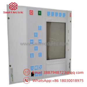
The ABB UNC4673A,V1 HIEE205014R0001 functions as the primary sensory interface unit within the UNITROL 5000 static excitation system architecture. This heavy-duty board serves as an absolute bridge between high-energy electrical infrastructure and the delicate digital processing environment of the controller rack. It captures real-time analog values directly from main generator stator terminals and excitation transformers, instantly scaling and converting these dangerous potential differences into digitized signals.
Field-commissioned by power generation engineers, the UNC4673A stands out due to its extreme precision components and galvanic isolation layers. By filtering out structural high-frequency noise and switching harmonics produced by the thyristor power bridges, it delivers clean, uncorrupted feedback arrays directly to the main regulation processor. This prevents feedback calculations from tracking harmonic distortion, eliminating false voltage fluctuations and maintaining reliable grid synchronization.
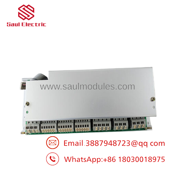
- UNC4673A
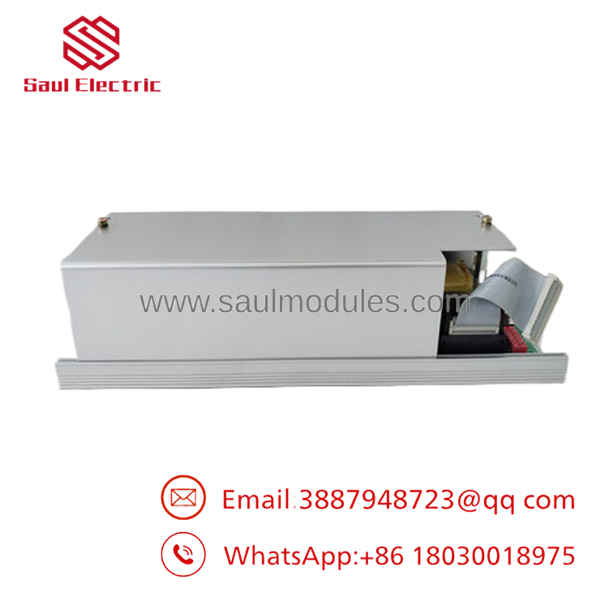
- UNC4673A
Installation & Configuration Guide
Stage 1: Pre-Installation Preparation (Estimated Time: 20 Minutes)
- ⚠️ Safety First: The UNC4673A interfaces directly with instrumentation transformers carrying hazardous potentials. Notify grid dispatchers of the outage. Lock out and tag out (LOTO) all primary potential transformer (PT) fuses, current transformer (CT) shorting blocks, and the 24 VDC rack control power links. Wait at least 15 minutes for any internal system capacitors to completely discharge. Verify zero-energy states across all terminal strip inputs using a properly rated multimeter before opening card retention latches.
- Tools Required: Grounded static-control (ESD) wrist strap, unpainted ground point clamp, precision insulated terminal drivers (flathead and PH2), fiber connector cleaning supplies, service laptop with UNITROL CMT (Configuration & Maintenance Tool).
- Data Backup: Connect your service laptop to the central system controller rack. Save a full archive of current excitation loop variables, gain multipliers, calibration constants, and network station addresses. Take clear smartphone images of the physical board jumpers, grounding links, and input block wire numbers.
Stage 2: Removing the Old Module (Estimated Time: 15 Minutes)
- Clamp your ESD wrist strap firmly onto a bare-metal structural frame point inside the excitation panel cubicle.
- Carefully label each wire on the heavy measurement terminal strips. Loosen the terminal blocks or multi-pin plugs and pull them back gently—never pull directly on the wire insulation.
- Disconnect any internal parallel bus ribbons or fiber link cables. Apply protective caps to open ports immediately.
- Back out the heavy-duty mounting screws pinning the 3.08 kg structural chassis to the rack frame assembly.
- Support the weight of the board firmly, disengage the locking tabs, and draw the card directly forward out of its mounting tray to prevent bending the backplane pins.
- ⚠️ Note: Keep this old unit resting safely on an ESD mat nearby to serve as a visual setup map for verifying hardware revisions and jumper arrays.
Stage 3: Installing the New Module (Estimated Time: 15 Minutes)
- Unseal the new surplus module from its anti-static shielding bag while maintaining secure grounding via your wrist strap.
- Configuration Clone (Crucial): Carefully cross-examine the physical jumper configurations on the new card against your old unit. The features distinct hardware jumpers used to select input signal ranges (e.g., 100V vs. 220V inputs) and configure bus termination logic. A mismatch here will lead to immediate overvoltage trips or component communication errors upon boot.
- Guide the module into its rack rails, ensuring it stays level until it aligns with the backplane, then press it firmly home until the connectors are fully seated.
- Tighten all structural mounting panel screws to complete the low-impedance frame ground circuit required for signal shielding.
- Reinstall the signal cables, checking that every wire terminal is properly seated and tightened.
- Self-Checklist:
- [ ] Onboard input scaling and bus termination jumpers precisely match the original board configuration.
- [ ] Heavy chassis framework is mounted flush with structural grounding screws securely tightened.
- [ ] Input terminal screws are properly torqued to prevent high-resistance contact points.
Stage 4: Power-On & Testing (Estimated Time: 25 Minutes)
- Pre-Power Check: Conduct a quick resistance check across the input terminals using a multimeter to rule out low-impedance line-to-frame short circuits on the newly installed hardware.
- Power-On Steps:
- Energize the 24 VDC logic control rail breaker only. Keep the main PT disconnects and CT blocks completely isolated at this point.
- Observe the internal status LEDs. The module should complete its power-on self-test (POST) sequence within 30 seconds, turning on a steady green power indicator. If a red fault or error light illuminates, verify system bus integrity.
- Log into the UNITROL engineering platform from your laptop. Open the diagnostic hardware tree to ensure the new card is recognized on the internal bus network.
- Perform an offset calibration of the analog input channels to compensate for trace variances on the new board.
- Restore the measurement transformer links, bring the machine up to nominal speed, and verify that the digitized voltage feedback values match the actual values read from your calibrated hand-held multimeter before closing the field breaker.
- ⚠️ Troubleshooting Note: If you see an immediate “Measurement Out of Range” alert on boot, power down and check whether the input voltage scaling jumpers were configured for the wrong potential transformer output ratio.
Frequently Asked Questions (FAQ)
Can the module be swapped while the UNITROL system is active?
No. Attempting a live swap will trigger an immediate emergency shutdown. The provides the core analog feedback loop variables used to calculate active thyristor firing commands. Removing this card while online will instantly break the regulation loop, resulting in an unmanaged loss of excitation fault and a generator trip. Always shut down the generator and ensure a zero-energy state before replacement.
Why is the physical weight of this interface card over 3 kg?
Unlike modern low-power microcontrollers, the is constructed with heavy-duty galvanic isolation barriers, substantial magnetic shielding plates, and ruggedized mounting components. This industrial design is necessary to protect the internal digital electronics from high common-mode voltage transients and intense magnetic fields found within high-power excitation cabinets.
What should I do if the new card displays a communication fault on startup?
This issue is typically caused by a mismatch in the bus station address settings or missing parallel bus termination. Power down the system, pull the card, and re-examine the manual DIP switches and jumper arrays. Ensure they exactly mirror the settings of your decommissioned unit, as factory replacements are shipped with standard default open configurations.
Is this an authentic product, given that the UNITROL 5000 is a legacy system?
Yes. Our units are authentic New Original / New Surplus components. They are sourced directly from canceled infrastructure capital projects, industrial surplus modernizations, or strategic utility backup reserves. They are entirely unused, have never been in service, and are preserved in climate-controlled warehouses within sealed anti-static packaging.
What kind of warranty backup is included with this measuring unit?
Every board includes a comprehensive 1-year replacement warranty from your delivery date. If the module experiences an operational failure or component defect under standard operating conditions within 12 months, we will supply a matching replacement module or issue a full refund if stock is no longer available.
Core Strategy 1: SOP Quality Transparency
To ensure high reliability and eliminate any concerns regarding surplus system components, all incoming measuring interface units go through our multi-phase quality inspection pipeline:
- Inbound Inspection & Traceability:
- Supply logs are cross-checked against commercial customs declarations and known industrial procurement records.
- Microscopic visual checks evaluate the PCB for solder-mask consistency, pristine factory silkscreen text, and genuine serial code plates.
- Component layout checks confirm that all onboard sub-components and connector terminals are fully intact and modification-free.
- Electrical Parameter Testing:
- Isolation resistance profiling is executed with a Fluke 1507 insulation tester at 500 VDC across internal power buses to ensure resistance values exceed 10 MΩ.
- Grounding continuity mapping confirms that the card’s low-impedance protection pathways are fully continuous to prevent floating noise issues in the field.
- Live Functional Testing:
- The card is installed inside an authentic ABB UNITROL test frame running a clean, stabilized 24 VDC input.
- Power-on self-test (POST) routines are analyzed to confirm proper processor boot cycles and accurate LED diagnostic behavior.
- Internal parallel bus links are coupled to network testing equipment to verify full data throughput performance with zero packet drops.
- Modules undergo an extended 24-hour heat burn-in process under load while infrared thermal imaging monitors for component hotspots or voltage fluctuations.
- An itemized QC Test Report is registered for your plant files; verification testing videos can be generated upon request before shipment.
- Firmware & Configuration Verification:
- The underlying firmware version is extracted, recorded, and cleared of old site settings.
- All hardware configuration elements are reset to default factory baselines, providing a clean slate for your system integration engineers.
- Final QC & Packaging Control:
- The supervising inspector confirms quality criteria compliance and signs off on the final tracking sheet.
- The board is encased inside an airtight, moisture-resistant anti-static (ESD) protective sleeve.
- It is packed using high-density bubble wrap inside custom, multi-wall corrugated cardboard shipping boxes to prevent shock damage during transit.
- The outer container is sealed with a dated “QC Passed” label.
Core Strategy 2: Technical Pitfall & Survival Guide
Replacing high-speed measurement modules in critical power electronics requires absolute precision. Avoid these 5 frequent installation mistakes:
- ❗ Mismatched Voltage Input Jumpers:
- The Trap: Installing a replacement card configured for alternative potential transformer signal levels will cause either massive measurement clipping or understated feedback metrics, causing an immediate system overvoltage trip on startup.
- Survival Strategy: Treat this as a vital step. Use your phone to snap a high-resolution photograph of the failed board’s scaling pins before you remove it. Use that photo to manually verify every jumper position on the new module before inserting it into the rack slot.
- ❗ Missing Channel Offset Calibration:
- The Trap: Directly running a newly swapped module without zero-point adjustment introduces micro-volt signal bias drift, skewing thyristor phase angles and leading to localized circuit imbalance.
- Survival Strategy: Always launch the UNITROL tuning package tool during the initial offline power phase. Complete a fresh sensor tracking calibration sequence to ensure accurate feedback calculations.
- ❗ Backplane Alignment Damage:
- The Trap: Forcing the heavy 3.08 kg card into a misaligned slot can bend or snap the fragile, high-density contact pins on the backplane connector, ruining the rack assembly.
- Survival Strategy: The board should slide smoothly along its guide rails without resistance. If you feel friction, do not jam the board in. Back it out, check for foreign objects inside the slot, look for bent pins with a flashlight, realign the card, and try again.
- ❗ Loose Wire Terminal Contacts:
- The Trap: Failing to fully torque down the analog measurement block screw anchors can create micro-arcing terminal boundaries or high resistance paths, distorting crucial sensor readings.
- Survival Strategy: Double-check every connection with an insulated screwdriver. Give each wire a gentle pull to ensure it is locked tightly into the terminal block.
- ❗ Latent Static Discharge Damage:
- The Trap: Handling sensitive electronic assemblies without adequate ESD equipment can introduce microscopic static damage to sensitive component arrays. This damage may not cause an immediate failure, but can manifest as random resets months down the line.
- Survival Strategy: Treat the board with care. Avoid making direct contact with the circuit board traces or edge pins. Always wear a grounded static wrist strap and complete your configuration on an approved anti-static workspace mat.


 Start Chat


