





Description
Key Technical Specifications
| Parameter | Specification Value |
|---|---|
| Board Classification | High Voltage Drive (HVD) Gate Driver & Sensor Board |
| System Application | UNITROL 6000 / MEGATROL power conversion cabinets |
| PCB Protective Finish | Full conformal coating for moisture, chemical, and conductive dust resistance |
| Onboard Energy Storage | Multi-cell electrolytic capacitor bank for stable gate pulse delivery |
| Signal Transmission | High-isolation pulse transformer circuits for thyristor triggering |
| Backplane Interfacing | Multi-pin heavy duty connector bus for system processor link |
| Monitoring Channels | Integrated voltage and thermal feedback diagnostic paths |
| Cooling Requirements | Forced air via power cabinet cooling fan layout |
| Dielectric Isolation | Reinforced high-voltage boundary insulation according to EN 50178 |
| Operating Temperature | -5 to +60 °C (+23 to +140 °F) ambient enclosure temperature |
Product Introduction
The ABB XVC770BE101 (3BHE021083R0101) is a specialized, high-reliability control card designed for heavy-duty power electronics, primarily serving within ABB UNITROL 6000 excitation systems and MEGATROL static frequency converters (SFC). This board acts as the critical physical interface between the low-voltage control processor computing section and the high-power thyristor components, directing firing pulses to manage generator rotor fields or heavy industrial motor starts.
Engineered with severe industrial environments in mind, the XVC770BE101 incorporates a robust conformal coating across its entire surface to prevent cross-track leakage and component breakdown caused by carbon soot, moisture, or chemical vapors. Its onboard layout features a series of high-capacity storage capacitors and isolated transformer paths that guarantee repeatable, crisp gate firing edge rates even during acute grid disturbance transients, making it a critical component for power plant availability.
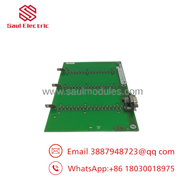
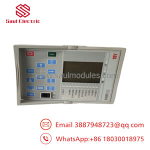
- XVC770BE101 3BHE021083R0101
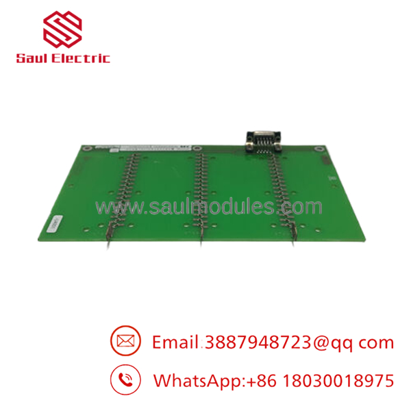
- XVC770BE101 3BHE021083R0101
Installation & Configuration Guide
Stage 1: Pre-Installation Preparation (Estimated Time: 25 minutes)
- ⚠️ Safety First: Excitation and high-power rectifier cabinets contain lethal DC and AC voltages. Isolate the main circuit breaker, safety switches, and tracking lines. Lock out and tag out (LOTO) all supplies. Wait at least 10 minutes for the internal high-energy power capacitors on the busbars and boards to completely discharge to ground. Confirm zero voltage with a high-voltage rated meter probe before crossing the cabinet threshold.
- Tools Required: Grounded static-safe (ESD) wrist strap, non-magnetic terminal screwdrivers, digital multimeter with insulated probes, and protective clean-room handling gloves.
- Data Backup: The XVC770BE101 is primarily an executive driver interface rather than a programmable processor. However, before extraction, record any hardware jumpers or physical configuration modifications present on the surface layout of the failing board.
Stage 2: Removing the Old Module (Estimated Time: 15 minutes)
- Affix your grounded ESD wrist strap to your wrist and a bare metal cabinet frame point.
- Carefully unplug the ribbon signals or fiber communication wires attached to the peripheral channels, being mindful not to stress or crimp the cables.
- Loosen the physical retaining screws fixing the card frame into the cabinet sub-rack or mounting standoff assembly.
- Grip the module firmly by its non-conductive pulling edges and draw it straight out from its female backplane socket receptacle to prevent terminal skewing.
- ⚠️ Note: Handle the board with extreme care; residual energy can linger in onboard components if the system was recently shutdown. Store inside an ESD protective shield bag immediately.
Stage 3: Installing the New Module (Estimated Time: 15 minutes)
- Keep the card inside its ESD packaging until the target sub-rack slot is prepped and clear of contaminants.
- Inspect the backplane slot to confirm no connector socket pins are broken or plugged with debris.
- Align the new XVC770BE101 board with the rack guide channels. Slide it forward gently until the rear-facing pin array meets the mating socket backplane.
- Apply firm, centered pressure until the board seats fully flush against the frame alignment pins.
- Secure all faceplate or board anchor screws to prevent loosening from ambient turbine floor vibration.
Stage 4: Power-On & Testing (Estimated Time: 30 minutes)
- Restore control-level auxiliary power to the cabinet first (keeping the main high-power incoming three-phase lines isolated).
- Verify that the system diagnostic processor reports a healthy peripheral board configuration without throwing bridge communication faults.
- Check the internal DC power rail voltages on the card at the designated test loops to confirm they sit within factory tolerances.
- Initiate a gate-pulse test sequence via the main UNITROL configuration terminal to confirm correct pulsing patterns are reaching the thyristor bridge layout.
- Once gate patterns pass validation, clear the cabinet space, secure all doors, and proceed to introduce full operational stator line voltage to the power bridge.
- ⚠️ Troubleshooting Note: If the master diagnostic engine registers an “Excitation Firing Fault” immediately after replacement, verify that the ribbon connector interface is completely flat and that no pins were recessed or bent during the backplane insertion step.
Frequently Asked Questions (FAQ)
Can I change this card while the generator is synchronized to the utility grid?
Absolutely not. The directly dictates the firing pulses for the main excitation thyristor deck. Pulling or adjusting this board while the generator is on-line will instantly disrupt the rotor magnetic field, causing a severe overcurrent or reverse-power trip that could destroy the power rectifier bridge components and damage the generator shaft structure.
Why does this board have a complete conformal coating while others do not?
Excitation and static frequency converter cabinets often utilize forced air cooling directly from the plant environment. Over time, this air introduces microscopic conductive pollutants, metallic dust, and moisture into the electronics rack. The heavy conformal coating forms an impermeable physical boundary layer that safeguards the surface conductor lines from tracking shorts and voltage flashovers.
Are the boards repairable if they suffer a gate pulse circuit failure?
While component-level repairs are technically possible, fixing high-power excitation boards on-site is highly discouraged by plant safety standards. The circuit traces must handle precise firing pulse rise times and high isolation parameters. A micro-fracture or off-spec component replacement could cause asynchronous firing, leading to damaging harmonic stress on the generator. It is always safer to install a certified New Surplus or factory-retested spare.
Does this board require any firmware flashing or software calibration after physical install?
No. The operates as an absolute hardware execution driver interface. It routes, filters, and isolates the high-speed timing commands generated by the upstream main controller processing unit. As long as any onboard physical jumper layout closely mirrors the module it replaces, the card is ready to run right out of the shipping carton.
How do I store a backup spare card long-term to ensure it works when needed?
Keep the module sealed inside its original moisture-barrier ESD shielding bag. Store it in a temperature-controlled, non-condensing environment between 15 and 30 °C. Because the board utilizes long-life electrolytic capacitors for gate energy delivery, keeping the storage zone free of severe thermal cycling will ensure the capacitors perform reliably when the board is called into live emergency service years later.


 Start Chat


