





Description
Product Introduction & Engineering Value
The Allen-Bradley 1756-IF6I is a premium analog input module engineered for critical process control applications where field signal integrity is paramount. Featuring true channel-to-channel optical and galvanic isolation, the “I” designation indicates that each of its 6 analog inputs operates with a completely independent electrical circuit reference.
By isolating every channel from both the backplane and adjacent field wiring, the 1756-IF6I prevents common-mode voltage spikes, ground potential differences, and electrical cross-talk from corrupting analog measurements. This makes it the ideal interface for long-distance transmitter runs, variable frequency drive feedback loops, and facilities with ungrounded power systems where standard non-isolated analog cards (like the 1756-IF8) suffer from signal drift or ground loop interference.
Technical Specifications
| Specification | Parameter Value |
| Module Type | Isolated Analog Input Module |
| Number of Inputs | 6 Individually Isolated Channels |
| Input Signal Ranges | ±10V DC, 0–10V DC, 0–5V DC, 0–20 mA, 4–20 mA |
| Analog-to-Digital Converter | 16-Bit Resolution (Sigma-Delta) |
| Isolation Voltage | 250V continuous (channel-to-channel & channel-to-backplane) |
| Input Impedance | > 1 MΩ (Voltage) / 249 Ω (Current) |
| Calibrated Accuracy | Better than 0.1% of range |
| Data Format | IEEE 32-bit Floating Point or Integer |
| Backplane Current (5.1V DC) | 250 mA |
| Backplane Current (24V DC) | 120 mA |
| Power Dissipation | 4.1 Watts |
| Removable Terminal Block (RTB) | 1756-TBCH or 1756-TBS6H (36-pin) |
| Operating Temperature | 0°C to 60°C (32°F to 140°F) |
Field Application & The “Trench” Experience
In a municipal wastewater treatment plant, flow meters and tank level transmitters located in separate outdoor pumping stations were connected back to a central ControlLogix PLC. Because the field instruments were powered by different electrical sub-panels with minor ground potential differences, a non-isolated analog card experienced persistent offset drift (up to ±15% error) on its 4–20 mA readings.
Replacing the non-isolated card with a 1756-IF6I module instantly resolved the measurement error. The 250V channel-to-channel optical isolation broke the ground loops completely, stabilizing the 4–20 mA current loops across all 6 outdoor flow channels without requiring external 3rd-party signal isolators.
- Heavy Industrial & Steel Rolling Mills: Monitoring drive tachometers and load cells where high-power VFD noise causes ground potential shifts.
- Chemical Process Batching: Precision monitoring of pH, pressure, and temperature transmitters connected across physically separated process skids.
- Power Generation & Substations: Reading transformer telemetry and battery bank voltages where high common-mode voltages exist.
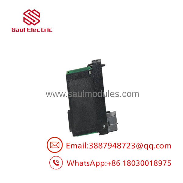
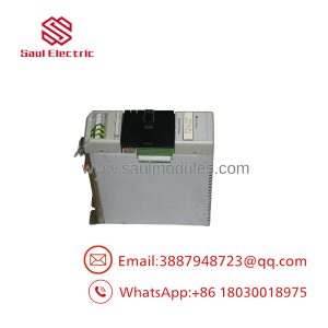
- 1756-IF6I
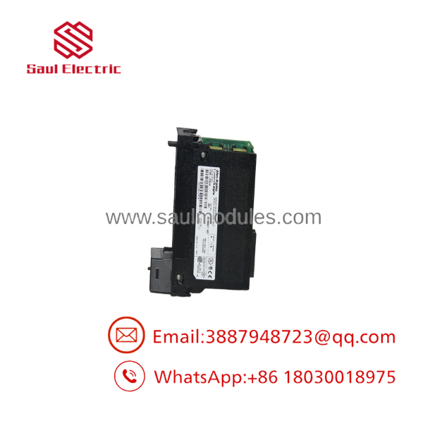
- 1756-IF6I
Transparency SOP: QA & Testing
- Terminal Pin & Optical Isolation Audit: Inspecting 36-pin RTB alignment guides, front status LEDs, backplane gold edge contacts, and internal isolation transformer integrity.
- Precision Signal Generator Calibration Check: Injecting high-precision 4.000 mA, 12.000 mA, and 20.000 mA current signals (as well as 0–10V steps) across all 6 channels to verify < 0.1% full-scale accuracy.
- High Common-Mode / Isolation Stress Test: Applying 100V DC differential potential between adjacent channels during active polling to confirm complete channel isolation and zero signal interference.
- Thermal Chamber Burn-In: Running full 6-channel analog acquisition inside a 60°C environmental test cell for 12 hours while monitoring analog drift and backplane current draw.
The Veteran’s Tech Trap Guide
- ⚠️ Current vs. Voltage Wiring Jumpers: The 1756-IF6I requires separate wiring connections at the 36-pin RTB for current (mA) vs. voltage (V) signals. For 4–20 mA current loops, you must jumper the
i(current) terminal to thev(voltage) terminal for that specific channel to engage the internal 249 Ω precision shunt resistor. - PRO TIP: 1756- vs. 1756-IF8 Differences: A standard 1756-IF8 offers 8 single-ended or 4 differential non-isolated channels. The offers 6 individually isolated channels. If replacing an IF8 with an , account for the lower channel count (6 vs 8) and different terminal pinouts in Studio 5000.
- ⚠️ 24V DC Auxiliary Power Requirement: Unlike standard voltage input cards, the 1756- draws 120 mA at 24V DC directly from the ControlLogix backplane to power its isolated onboard A/D converters. Ensure your chassis power supply (e.g., 1756-PA72 or 1756-PB72) has sufficient 24V DC headroom.
Dynamic FAQ
Q: Does the 1756- provide loop power for 2-wire transmitters?
A: No. The 1756- is an analog input signal processing module and does not supply field 24V DC loop power. 2-wire 4–20 mA transmitters require an external 24V DC power supply wired in series with the loop.
Q: Which removable terminal block (RTB) is required for the 1756-?
A: The module requires a 36-pin terminal block—either the 1756-TBCH (cage-clamp) or 1756-TBS6H (spring-clamp). Standard 20-pin RTBs are not compatible.
Q: Can I mix voltage and current input signals on the same 1756- module?
A: Yes. Because every channel is individually isolated and independently configured in Studio 5000 / RSLogix 5000, Channel 0 can be configured for 4–20 mA while Channel 1 is configured for ±10V DC.
Q: Are replacement 1756- modules fully bench-tested prior to shipping?
A: Yes. Every 1756- module undergoes 6-channel precision signal calibration, channel-to-channel isolation stress verification, backplane power check, and 12-hour thermal burn-in.

 Start Chat


