





Description
Product Introduction
The Allen-Bradley 1794-TB3 is a 3-wire screw-clamp terminal base unit engineered for the modular FLEX I/O platform. It forms the essential physical and electrical foundation of a FLEX I/O station, housing the field wiring terminals, power distribution buses, and the interconnecting Flexbus backplane ribbon interface.
Designed specifically for 16-point digital or analog modules requiring 3-wire field terminations (Signal, Power (+V), and Common (COM)), the 1794-TB3 allows engineers to land 2-wire and 3-wire proximity sensors, photoeyes, or transmitters directly onto the base without adding external terminal blocks. Because all field wiring attaches directly to the 1794-TB3 base, I/O modules can be snapped on or removed under power (RIUP) without disturbing permanent panel wiring.
Key Technical Specifications
| Parameter | Value |
| Number of Terminals | 36 Screw-Clamp Terminals (3 Tiers: 16 Signal, 8 Common, 8 Voltage (+V), 4 Common/Voltage Power Terminals) |
| Terminal Wire Size | 0.21 to 1.3 mm^2 (24 to 16 AWG) Solid or Stranded Copper Wire |
| Screw Torque | 0.5 to 0.6 Nm (5 to 7 lb-in) |
| Maximum Voltage Rating | 125V AC / DC |
| Current Capacity | 10 A Maximum through Power Terminals |
| Flexbus Rating | 5V DC, 640 mA Pass-Through |
| Dimensions (H x W x D) | 94 x 94 x 69 mm (3.7 x 3.7 x 2.7 in) |
| Mounting Style | DIN Rail (35mm) or Direct Panel Wall Mount |
| Keying Positions | 1 through 12 Adjustable Mechanical Rotary Dial |
Application Scenarios & The “Trench” Experience
Picture this: A maintenance crew is retrofitting a cabinet on a packaging line containing 16 3-wire PNP proximity switches. If they used a standard 2-wire base (like the 1794-TB2), they’d have to mount a separate DIN-rail terminal strip above the I/O rack just to jump the 24V DC auxiliary power and common wires to all 16 sensors, cluttering the panel and doubling wiring labor. Installing the 3-tiered 1794-TB3 base provides a dedicated Signal terminal on the top row, Common on the middle row, and Voltage on the bottom row for every single channel, keeping the enclosure clean, traceable, and fast to commission.
- Automotive Assembly Cells – High-Density Proximity Sensor Racks – Distributes 24V DC field power directly to 3-wire inductive sensors without auxiliary terminal blocks.
- Food & Beverage Conveyors – Photoeye & Limit Switch Networks – Connects multi-conductor field drops directly to FLEX I/O modules mounted in distributed junction boxes.
- Water & Wastewater Lift Stations – Instrument Telemetry – Routes 3-wire process transmitters (signal, supply, ground) back to centralized EtherNet/IP adapter nodes.
- OEM Machinery Enclosures – Compact Modular Panel Builds – Reduces total enclosure footprint by integrating wire distribution buses straight into the module base plate.
Field Case Study: A plastic extrusion plant in Indiana suffered intermittent signal dropouts on a thermal control loop. Technicians traced the fault to a cracked terminal block frame on an old base where a technician had over-tightened the screw clamps during a shift change. Sourcing a fresh 1794-TB3 base allowed them to quickly transfer the existing field wires to the new tier blocks, lock the analog module into place, and restore thermal monitoring before the extruder barrels cooled down.
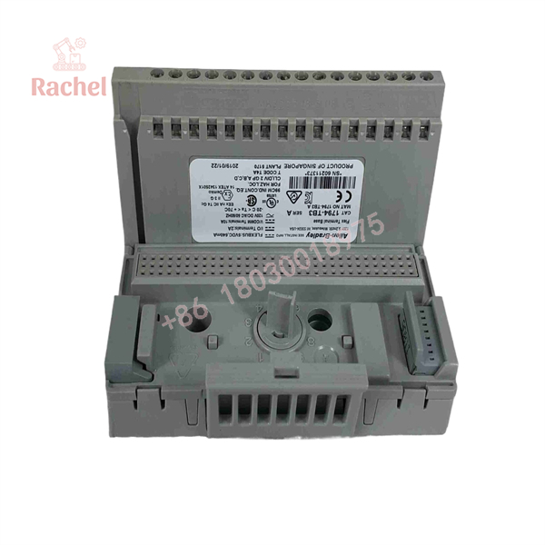
1794-TB3
Transparency SOP: Quality Assurance & Testing
We don’t just ship boxes; we inspect and bench-verify every component. Every 1794-TB3 terminal base undergoes our strict 5-stage verification process:
- Inbound Physical Inspection: Inspect all plastic housing latches, DIN rail spring clips, keyswitch rotary dial mechanisms, and verify that no terminal screws are stripped or missing.
- Backplane Connector Audit: Inspect male and female Flexbus side connectors for bent pins, corrosion, or debris that could interrupt backplane power or communication.
- Continuity & Short Circuit Verification: Test continuity across each tier of screw terminals (Signal, COM, and +V) to confirm zero internal short circuits across adjacent channels.
- Mechanical Module Engagement Test: Seat a known-good FLEX I/O module onto the base to verify smooth latching, pin alignment, and proper keyswitch clearance.
- ESD Cleaning & Protective Packaging: Clean body with anti-static solution, pack with terminal protection, and seal inside protective anti-static wrap.
The Veteran’s Tech Trap Guide (Crucial Value-Add)
- ⚠️ Set the Mechanical Keyswitch BEFORE Inserting the Module! The 1794-TB3 features a orange rotary keyswitch dial on the upper left. You MUST turn this dial to match the specific keyswitch position required by your I/O card (e.g., Position 2 for a 1794-IB16, Position 3 for a 1794-OE4). Attempting to plug a module into a base set to the wrong number will bend the pins or crack the housing!
- ❗ Do Not Over-Torque Terminal Screws: The cage-clamp screws on the 1794-TB3 are rated for a maximum torque of 5 to 7 lb-in (0.5 to 0.6 Nm). Using an electric driver or over-tightening can strip the internal brass threads, forcing a complete replacement of the base.
- ⚠️ Verify Power Jumper Capacity (10A Limit): The internal power rails on the 1794-TB3 are rated for a maximum of 10 Amps continuous. If you are daisy-chaining field power across multiple 1794-TB3 bases in a long rack, calculate total field sensor current draw to ensure you don’t exceed 10A on the primary supply terminals.
- ❗ Align Flexbus Connectors Straight: When sliding adjacent 1794-TB3 bases together on a DIN rail to form a rack, ensure they snap together completely flat. Angled or partial insertion of the flexbus connector can cause backplane communication faults across the downstream modules.
Frequently Asked Questions (FAQ for Conversion)
Q: What is the difference between the 1794-TB3 and the 1794-TB3S?
A: The 1794-TB3 features standard screw-clamp terminals, whereas the 1794-TB3S utilizes spring-clamp (push-in) terminals. Both offer the exact same 3-wire tier layout and electrical specifications.
Q: Does the 1794-TB3 include the FLEX I/O module?
A: No. The 1794-TB3 is the base unit only. The active electronic modules (such as 1794-IB16, 1794-OW8, or 1794-IE8) and network adapters (1794-AENT) are sold separately.
Q: Can I use the 1794-TB3 with 2-wire field devices?
A: Yes. You can land 2-wire devices on the Signal and Voltage (or Common) terminals. The 3-wire base gives you the added flexibility to support 2-wire, 3-wire, or 4-wire field instruments on the same block.
Q: Is the 1794-TB3 compatible with Extended Temperature (XT) modules?
A: Yes, but for harsh or extreme environments (-20 °C to +70 °C), Rockwell recommends the conformal-coated 1794-TB3K variant to prevent corrosion from moisture and harsh chemical atmospheres.
Q: Why buy New Surplus terminal bases from us?
A: Terminal bases are often overlooked until a panel upgrade or emergency repair reveals a cracked or stripped unit. Sourcing on-the-shelf surplus guarantees immediate delivery without waiting weeks for distributor factory shipments.
Q: What warranty is included with this base unit?
A: All our 1794-TB3 base units (New Surplus or Bench-Tested) come backed by our full 12-month functional replacement warranty.

 Start Chat


