





Description
Product Introduction
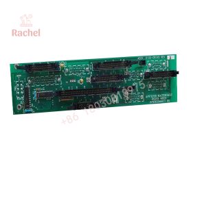
The Applied Materials 0100-09123 is a dedicated optical wafer sensor circuit board designed for AMAT semiconductor manufacturing equipment, including Precision 5000, Endura, and Centura processing chambers. Installed directly near robot blade assemblies, cassette indexing positions, or transfer chamber blade combs, this module provides low-latency optical sensing of wafer presence, alignment, and blade position.
Featuring onboard signal comparators, voltage regulation, and diagnostic LEDs, the 0100-09123 converts raw opto-interrupter signals into clean digital logic inputs for the central tool controller. Replacing a degraded or drift-prone wafer sensor board eliminates false “No Wafer Present” alarms, robot blade interlock trips, and wafer placement misalignments during automated production runs.
Key Technical Specifications
| Parameter | Value |
| Manufacturer | Applied Materials (AMAT) |
| Assembly Part Number | 0100-09123 |
| Board Category | Optical Wafer Sensing / Robot Comb Opto Interface |
| Tool Compatibility | AMAT Precision 5000, Centura, Endura Series |
| Signal Inputs | Optical Wafer Sensor / Robot Comb Opto Harnesses |
| Diagnostic Features | Onboard Red LED Status Indicators (DS1–DS4) |
| Interface Connectors | Multi-Pin Header Connectors (P1, P2, P3, P4) |
| Mounting Type | Direct Standoff Mount (Internal Tool Sub-Chassis) |
| Operating Temp | 10°C to 50°C (50°F to 122°F) |
Application Scenarios & The “Trench” Experience
When an optical wafer sensor board fails inside a vacuum transfer chamber or loadlock module, the tool software immediately halts the transfer sequence. If a single opto-coupler channel fails to register a wafer on the end-effector, the tool will throw an unhandled “Wafer Lost” fault—risking costly wafer breakage or improper chamber loading. In field environments, ambient chemical outgassing and thermal cycling inside process bays are leading causes behind component drift and LED emitter degradation on the 0100-09123 PCB.
- Wafer Handling Robotics – Robot Blade & Comb Opto Sensing – Verifies wafer presence and blade retracted/extended positions prior to chamber entry.
- Cassette Indexing & Loadlocks – Position Verification – Ensures precise vertical indexing alignment before robot pick-and-place operations.
- Process Chamber Interlocks – Safety Hardware Polling – Sends direct hardware feedback to prevent gate valves from closing on misaligned substrates.
Field Case Study
An etch chamber on a 200mm Centura tool repeatedly triggered false “Wafer Sensor Fault” errors, causing intermittent aborted runs during transfer cycles. Technicians checked the optical sensors, but determined the signal degradation was occurring on the signal processing board. Replacing the failing unit with a pre-tested 0100-09123 wafer sensor board restored clear signal thresholds. The onboard diagnostic LEDs confirmed stable optical handshakes, and the tool returned to full 24/7 production within 30 minutes.
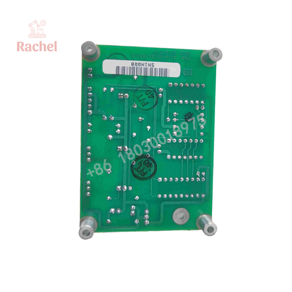
0100-09123
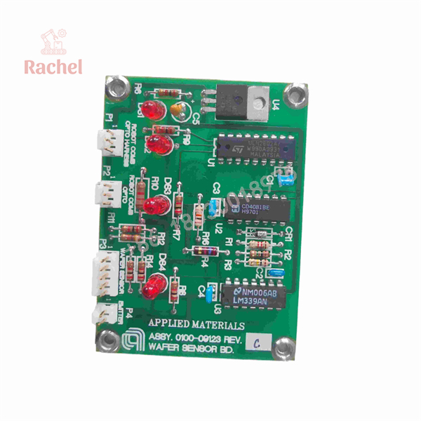
0100-09123
Transparency SOP: Quality Assurance & Testing
Every AMAT 0100-09123 board undergoes strict bench validation prior to inventory entry:
- Inbound Microscopic Inspection: Checking for burnt resistors, solder joint fatigue, trace oxidation, and verifying physical pin integrity on headers P1 through P4.
- Static Power Rail Audit: Verifying onboard voltage regulators (e.g., LM340/LM7815 rails) to ensure stable DC power delivery across IC comparators.
- Optical Signal Simulation: Injecting reference photo-interrupter inputs to verify clean switching logic, comparator thresholds, and instant LED status illumination.
- Thermal Stability Audit: Testing board logic under nominal operating temperature ranges to confirm zero component drift or intermittent signal dropouts.
- Anti-Static & Moisture Shielding: Vacuum-sealed inside ESD shielding bags with desiccant and packed in custom protective boxes for shipping.
The Veteran’s Tech Trap Guide
- ⚠️ Inspect Cable Harnesses During Swap: Corroded or pinched wires in the robot comb opto harness can mimic a board failure. Always check header cables (P1–P4) for bent pins or wire strain when installing the 0100-09123.
- ❗ Never Connect Under Power: Power down the local 24V/15V DC control bus before disconnecting or reconnecting header plugs. Hot-plugging sensor harnesses can damage sensitive onboard comparator ICs (such as LM339 series).
- ⚠️ Re-Calibrate Optical Sensors Post-Installation: After replacing the sensor PCB, perform a standard wafer sensor calibration through the AMAT tool interface to ensure threshold voltages match current photo-emitter levels.
- ❗ Follow Strict ESD Safeguards: Wear a grounded wrist strap at all times when handling bare PCBs to prevent electrostatic discharge damage to delicate CMOS logic gates.
Frequently Asked Questions (FAQ for Conversion)
Q: Is the AMAT 0100-09123 board hot-swappable?
A: No. Power to the sensor sub-chassis must be isolated before replacing the board to prevent electrical transients from damaging onboard ICs.
Q: What do the onboard LEDs (DS1–DS4) indicate?
A: The onboard LEDs provide direct visual feedback for optical channel states (such as wafer presence and comb sensor trigger states), allowing fast troubleshooting right at the board level.
Q: Why choose pre-tested surplus AMAT boards over long OEM lead times?
A: Many legacy AMAT 0100-series boards are obsolete or face long factory lead times. Pre-tested surplus units ship immediately to resolve emergency tool downtime at a fraction of the cost.
Q: How do you verify the board’s optical logic isn’t degraded?
A: Each board is bench-tested with real-time signal injection across all input headers to confirm crisp logic state switching and stable voltage regulation.
Q: What warranty is included with this replacement board?
A: All our reconditioned and surplus Applied Materials circuit boards come backed by a full 12-month replacement warranty.

 Start Chat


