





Description
Product Introduction
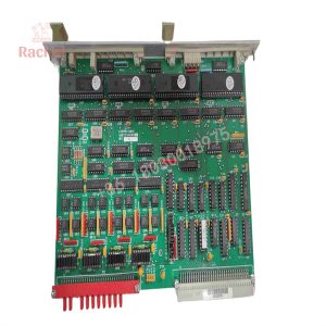
The Applied Materials 0100-71311 is a dedicated VME bus controller interface board designed for high-reliability process tools in semiconductor manufacturing. Installed into standard 6U VME chassis backplanes across AMAT and AKT platforms, this board handles deterministic control signal routing, local data buffering, and real-time handshaking between the central machine CPU and peripheral hardware interfaces.
Engineered to operate in demanding cleanroom electrical environments, the 0100-71311 offloads critical timing loops and bus traffic management from the primary tool processor. This hardware separation prevents comms timeouts during sensitive process steps, ensuring consistent execution of gas flow control, temperature regulation, and vacuum interlock sequences.
Key Technical Specifications
| Parameter | Specification |
| Manufacturer | Applied Materials (AMAT) |
| Part Number | 0100-71311 |
| Board Type | VMEbus Interface / System Controller |
| Form Factor | 6U Eurocard Standard (Single-Slot) |
| Bus Standard | IEEE 1014 VMEbus Compliant |
| Connectors | DIN 41612 P1 and P2 Backplane Headers |
| Operating Temperature | 0°C to +55°C |
| Power Input | +5VDC / ±12VDC (Supplied via VME Backplane) |
| Status Display | Onboard Front-Panel Diagnostic LED Status Array |
Application Scenarios & The “Trench” Experience
When a VME communication board fails on a wafer processing tool, the host controller loses real-time visibility into peripheral hardware. The tool immediately triggers an emergency stop, aborting active recipes, dumping vacuum, and potentially ruining high-value wafers inside the chamber. In a 24/7 fab, every hour spent troubleshooting or waiting on obsolete OEM hardware bleeds tens of thousands of dollars.
- Semiconductor – Etch & Deposition Tools: Manages high-speed data exchanges between host control racks and chamber sub-controllers.
- Semiconductor – Chemical Mechanical Planarization (CMP): Controls sensor acquisition loops and actuator positioning logic across multi-station platforms.
- Flat Panel Display – AKT Systems: Acts as a primary communication node across large-format glass handling racks.
During a night-shift escalation at a 300mm wafer fab, an etch cluster tool dropped offline with persistent bus communication errors. The field service team pinpointed the issue to a failing bus driver IC on the 0100-71311 controller card. Replacing the faulty board with a pre-tested, jumper-matched 0100-71311 replacement restored backplane communication right away, getting the chamber re-qualified and back into production before the morning shift started.
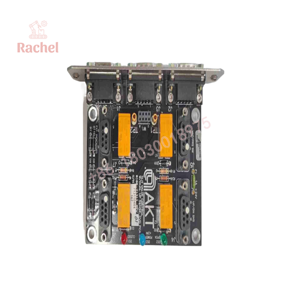
0100-71311
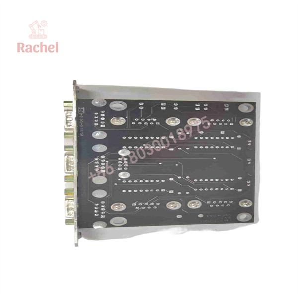
0100-71311
Transparency SOP: Quality Assurance & Testing
We understand that installing faulty surplus hardware in a semiconductor cleanroom is not an option. Every 0100-71311 unit goes through a thorough bench inspection and testing workflow:
- Inbound Visual & Structural Inspection: Microscopic verification of board traces, solder joints, onboard capacitors, and IC pin alignments to detect signs of heat degradation or physical damage.
- Connector Integrity Check: High-magnification check of P1/P2 backplane gold contacts to verify zero corrosion, wear, or bent pins.
- Powered Bench Test: Insertion into a dedicated 6U VME powered test rack to measure power rail stability and verify clock distribution logic.
- Bus Loopback & Stress Test: Execution of communication handshakes and simulated data transfer passes across the VME bus to confirm no packet loss or arbitration delay.
- ESD-Safe Preparation: Application of pin guards and vacuum-sealing in static-shielding moisture-barrier packaging.
The Veteran’s Tech Trap Guide (Crucial Value-Add)
⚠️ Never Pull This Card Hot: Standard VMEbus backplanes do not feature hot-swap protection circuitry on data lines. Inserting or removing the 0100-71311 while the VME rack is powered will cause voltage transients that can destroy bus transceiver ICs on this board and adjacent cards in the rack. Turn off system power completely before removal.
❗ Match Your Jumper Settings: Before installing a replacement board, lay your old card side-by-side with the new unit. Verify every hardware jumper and DIP switch position. AMAT uses these jumpers to define base memory addresses, interrupt levels, and bus priority—if these don’t match, the tool software will fail to identify the board on boot.
⚠️ Check P1/P2 Backplane Alignment: VME backplane pins are easy to damage if the card is pushed into the rack at an angle. Guide the 0100-71311 carefully along the chassis rails, and use the card ejector handles to seat the board evenly into the backplane connectors.
Frequently Asked Questions
Q: Is the AMAT 0100-71311 drop-in compatible with all VME chassis?
A: It is physically compatible with standard 6U VME card cages, but it requires correct jumper configuration and system software support specific to AMAT/AKT tool platforms to function correctly.
Q: Does this card require firmware flashing upon installation?
A: Generally, no. Most onboard logic is handled via hardware circuitry and onboard ROM/PLDs. However, ensure hardware revision levels match your original unit to maintain system software compatibility.
Q: Why choose surplus 0100-71311 boards instead of going through the original OEM?
A: AMAT has designated many legacy tool components as EOL (End of Life), leading to months-long lead times or non-availability. Sourcing high-quality surplus gets your production line back up without waiting on extended lead times.
Q: How do I know if my issue is the 0100-71311 board or the VME backplane itself?
A: Check the onboard diagnostic LEDs first. If the card fails power-on self-tests or shows persistent SYSFAIL errors while power rails are within tolerance, the board itself is likely faulty.
Q: What warranty is provided with this unit?
A: All our fully tested surplus and replacement modules come with a 12-month functional warranty from the date of receipt.

 Start Chat


