





Description
Core Product Summary (Brand / Model / Key Attributes)
The DEIF EPQ96-2 is a digitally controlled electronic potentiometer for panel mounting, designed to replace conventional motor-operated potentiometers in electronic speed-governor control circuits. It converts discrete raise/lower commands from a PI step controller into an analog voltage/current signal or PWM signal for an electronic governor.
The EPQ96-2 provides manual and automatic operating modes, configurable output start and end values, preset and last-value power-up behavior, and an adjustable integration time. Its analog output is selectable between −10 to 0 to +10 V DC and −20 to 0 to +20 mA DC, while PWM outputs provide a 0–6 V, 500 Hz signal. The unit also includes a J1939 CAN input that can convert a standard TSC1 telegram into analog or PWM output. It uses a 96 × 96 mm panel-mount housing with a 92 × 92 mm cutout and is supplied from 9–31.2 V DC.
Key Technical Specifications
| Attribute | Value |
|---|---|
| Brand | DEIF |
| Model | EPQ96-2 |
| Product type | Electronic potentiometer for panel mounting |
| Primary function | Converts discrete PI-controller relay outputs into governor/AVR control signals |
| Supply voltage | 9–31.2 V DC (12–24 V DC −25% / +30%) |
| Supply behavior | Continues operation down to 5 V |
| Analog output | −10 to 0 to +10 V DC or −20 to 0 to +20 mA DC |
| Analog output impedance | 500 Ω |
| Current-output load | Maximum 500 Ω |
| PWM outputs | Two outputs, 0–6 V at 500 Hz ±50 Hz |
| PWM resolution | 10,000 steps, greater than 13 bits |
| PWM response | Less than 0.1 s |
| Control inputs | Preset, raise, and lower; 9–31.2 V DC |
| Input current | 10 mA at 24 V DC |
| Input isolation | Preset, raise, and lower inputs are mutually galvanically isolated |
| CAN interface | J1939 CAN input; converts TSC1 telegram to analog or PWM output |
| Integration time | 2.5–25 s or 12.5–125 s |
| Setpoint resolution | 10-bit |
| Resolution | 2.5 mV or 5 µA RMS, 13-bit |
| Reproduction accuracy | ±0.5% |
| Ripple | 2.5 mV or 5 µA |
| Response time | Less than 0.1 s |
| Relay outputs | Auto/manual and status contacts; maximum 30 V AC/DC, 50 mA |
| Panel size | 96 × 96 mm front panel |
| Panel cutout | 92 × 92 mm |
| Terminal capacity | 2.5 mm² stranded or 4 mm² solid; CAN and status output: 1 mm² |
| Ingress protection | IP52 front panel; IP20 rear |
| Ambient temperature | −25 to +70 °C operating; −40 to +70 °C storage |
| Safety category | 300 V, Category III, Pollution Degree 2, IEC 61010-1 |
| EMC | IEC 61000-6-1, -2, -3, -4 and IEC 60255-22-1 |
| Housing material | Self-extinguishing polycarbonate, UL94 V-0 |
| Marking | CE |
Detailed Product Overview
The DEIF EPQ96-2 is a panel-mounted electronic potentiometer intended for speed-governor and voltage-regulator control in generator, propulsion, and engine-control installations. It replaces a motor-driven potentiometer with an electronic setpoint generator, eliminating the mechanical potentiometer drive while retaining familiar raise/lower control behavior.
In automatic mode, the EPQ96-2 receives discrete commands from a controlling device and translates them into a controlled output signal. The documented automatic-control sources include DEIF FAS-113DG and FAS-115DG synchronizers and DEIF LSU-112DG, LSU-113DG, and LSU-114DG load-sharing units. In manual mode, an operator uses the front-panel raise and lower buttons to adjust the output. The unit always returns to automatic mode after power-up.
The output can be configured as a bipolar analog voltage or current signal, or as PWM. The analog output is intended for governors or automatic voltage regulators that accept a ±10 V or ±20 mA control signal. The PWM outputs use a 0–6 V, 500 Hz signal; one PWM output follows the selected control value, while the other is a fixed output adjusted with a rear-panel potentiometer for functions such as governor droop setting. The PWM outputs are not galvanically isolated and share a common terminal.
A J1939 CAN input allows the EPQ96-2 to receive a standard TSC1 telegram and convert it into an analog or PWM command. This makes the unit suitable where a modern CAN-based control system must interface with a governor or AVR requiring an analog or PWM input. The minimum and maximum output limits remain active during CAN control, preventing the output from moving outside the commissioned range.
Power-loss behavior is configurable. The unit can reset to a preset value or restore the output value present before the supply interruption. On internal fault or loss of supply, the output relay opens the electronic output path and leaves a 500 Ω resistor connected across the output terminals, supporting local manual control of the connected governor or AVR.
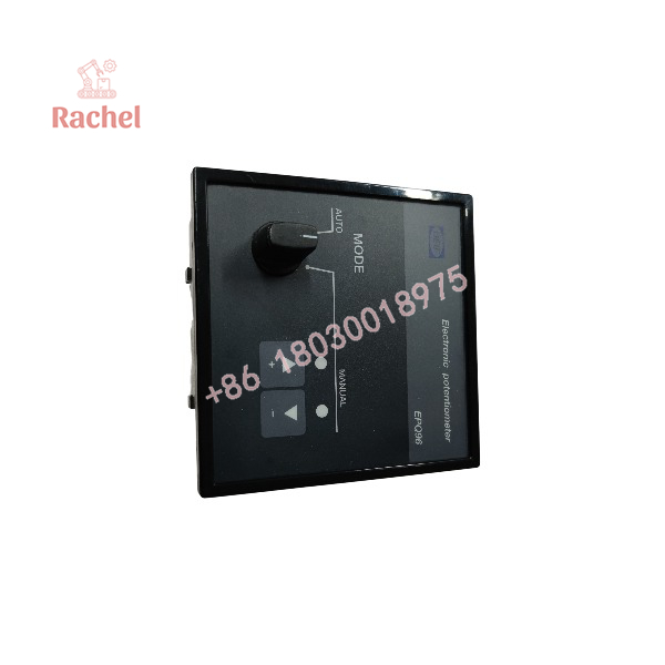
EPQ96-2
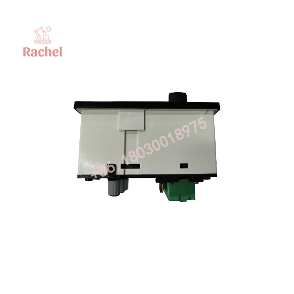
EPQ96-2
Engineering Selection Highlights
- The EPQ96-2 replaces a motor potentiometer in an electronic governor circuit, so it is appropriate where raise/lower discrete commands must produce a continuously variable governor or AVR setpoint.
- It accepts discrete outputs from specified DEIF FAS and LSU units, making signal-source compatibility a key selection check in DEIF-based synchronizing or load-sharing systems.
- Its selectable ±10 V or ±20 mA analog output covers common governor/AVR input requirements, but the connected device’s input impedance and signal polarity must suit the 500 Ω output architecture.
- Two 0–6 V, 500 Hz PWM outputs support PWM-controlled governors and droop adjustment, with the important constraint that these outputs are not galvanically isolated.
- The J1939 CAN input converts TSC1 telegrams to analog or PWM, allowing integration between CAN-based controls and legacy analog or PWM governor hardware.
- The 96 × 96 mm panel format and 92 × 92 mm cutout determine mechanical fit, while IP52 front/IP20 rear protection defines the suitable panel environment.
- Configurable preset and last-value power-up behavior affects recovery after supply interruptions, so the required post-outage setpoint should be defined during commissioning.
System Compatibility & Integration Requirements
| Item / Dependency | Verified Compatibility or Requirement | Practical Note |
|---|---|---|
| Automatic command source | DEIF FAS-113DG or FAS-115DG synchronizer | Provides discrete raise/lower commands for automatic speed control. |
| Automatic command source | DEIF LSU-112DG, LSU-113DG, or LSU-114DG load-sharing unit | Provides discrete raise/lower commands for automatic control. |
| Governor / AVR interface | −10 to 0 to +10 V DC or −20 to 0 to +20 mA DC analog input | Select and configure the output type to match the connected device. |
| PWM governor interface | 0–6 V, 500 Hz PWM input | One PWM output is controlled; the other is fixed and adjustable for droop. |
| CAN control system | J1939 CAN input accepting TSC1 telegram | Converts CAN commands to analog or PWM output; CAN bus termination may require a 120 Ω resistor. |
| Control inputs | Preset, raise, and lower inputs at 9–31.2 V DC | Inputs are mutually isolated. |
| Panel installation | 96 × 96 mm front panel, 92 × 92 mm cutout | Confirm panel thickness and rear clearance before installation. |
| Power supply | 9–31.2 V DC | The unit continues operating down to 5 V. |
Dimensions, Mounting & Connection Notes
- The front panel measures 96 × 96 mm and requires a 92 × 92 mm panel cutout.
- The housing is intended for panel mounting.
- Screw terminals accept 2.5 mm² stranded or 4 mm² solid conductors; CAN and status-output terminals accept 1 mm² conductors.
- The front panel is rated IP52; the rear is rated IP20.
- The unit operates from 9–31.2 V DC and includes surge protection according to IEC 7637-2.
- The analog output circuit uses a 500 Ω output resistance; the current output supports a maximum load of 500 Ω.
- PWM outputs are open-collector outputs with a 1 kΩ resistor connected to an internal 6 V supply; they share a common terminal and are not galvanically isolated.
- For CAN wiring, the documentation shows a CAN H, CAN L, and common arrangement; a 120 Ω bus-end termination resistor may be required. If communication is interrupted, the documentation notes that the screen connection at terminal 5 may be removed as a troubleshooting step.
FAQ
What is the DEIF EPQ96-2?
It is a digitally controlled, panel-mounted electronic potentiometer that replaces a motor potentiometer for controlling an electronic speed governor or automatic voltage regulator.
What signals does the EPQ96-2 produce?
It produces a selectable −10 to 0 to +10 V DC or −20 to 0 to +20 mA DC analog output, plus two 0–6 V, 500 Hz PWM outputs.
Can the EPQ96-2 be controlled from a CAN network?
Yes. Its J1939 CAN input can receive a standard TSC1 telegram and convert it into an analog or PWM output signal.
Which DEIF devices can command it automatically?
The documented automatic-control sources are DEIF FAS-113DG and FAS-115DG synchronizers and DEIF LSU-112DG, LSU-113DG, and LSU-114DG load-sharing units.
What supply voltage does it require?
It operates from 9–31.2 V DC and continues operating down to 5 V.
What panel cutout does it need?
It uses a 96 × 96 mm front panel and requires a 92 × 92 mm mounting cutout.
What happens after a supply interruption?
The EPQ96-2 can be configured either to reset to a preset output value or to restore the output value present before the interruption.
What protection ratings apply?
The front panel is IP52 and the rear is IP20, according to IEC and EN 60529.
Verification & Troubleshooting Notes
- Confirm the configured output type—voltage, current, or PWM—against the input requirement of the connected governor or AVR.
- Check that the raise, lower, and preset inputs receive the specified 9–31.2 V DC command signals.
- In automatic mode, verify the discrete command source and wiring from the FAS or LSU unit before adjusting the EPQ96-2.
- If CAN communication is not received, check CAN H/L polarity, bus termination, shielding, and the screen connection at terminal 5.
- The green power LED flashes once per second during an internal fault, and the status relay opens; investigate supply, wiring, configuration, and connected-device compatibility rather than bypassing the fault condition.
- The yellow raise/lower LEDs indicate active commands; a flashing LED indicates that the corresponding output has reached its maximum limit.
- Do not assume the PWM outputs are isolated: they share a common terminal and require careful grounding and shielding practice.

 Start Chat


