





Description
Core Product Summary (Brand / Model / Key Attributes)
The Foxboro FBM07 is a Contact/dc Input Interface Module for the Foxboro I/A Series distributed control system. As a 100 Series Fieldbus Module, it serves as an expandable main module that converts discrete field signals into digital data for the redundant module Fieldbus.
It provides 16 independent channels that can operate as contact sensors (with internal 24 V DC excitation) or as DC voltage monitors. The module supports configurable input filtering, channel isolation capable of withstanding 1250 V ac to ground, and pairs with an optional FBM12 expansion module for additional channels. Power is supplied via a redundant 26–42 V DC input, with maximum consumption of 7 W for the main module alone.
Key Technical Specifications
| Parameter | Specification |
|---|---|
| Product Type | Contact/dc Input Interface Module (expandable main) |
| Channels | 16 independent |
| Functions | Contact sensor or DC voltage monitor (selectable by configuration/wiring) |
| Isolation | Withstands 1250 V ac for 1 minute, channel to earth (ground) |
| Filter/Debounce Time | Configurable: 4, 8, 16, or 32 ms |
| Contact Sensor – Open-Circuit Voltage | 24 V dc ±10% |
| Contact Sensor – Short-Circuit Current | 2.5 mA maximum |
| Contact Sensor – ON-State Resistance | 1 kΩ maximum |
| Contact Sensor – OFF-State Resistance | 100 kΩ minimum |
| Voltage Monitor – ON-State Voltage | 15 to 130 V dc |
| Voltage Monitor – OFF-State Voltage | 0 to 5 V dc |
| Voltage Monitor – Current | 2.2 mA typical (5 to 130 V dc) |
| Power Input (Redundant) | 26 to 42 V dc |
| Power Consumption | Main module only: 7 W maximum; Main + expansion: 12 W maximum |
| Heat Dissipation | Main module only: 12 W maximum; Main + expansion: 22 W maximum |
| Operating Temperature | 0 to 60 °C (32 to 140 °F) |
| Relative Humidity | 5 to 95 % (non-condensing) |
| Storage Temperature | –40 to +70 °C (–40 to +158 °F) |
| Associated Expansion | FBM12 Contact/dc Expansion Input Interface Module |
| System | Foxboro I/A Series (100 Series FBM subsystem) |
Detailed Product Overview
The Foxboro FBM07 functions as a discrete input interface within the I/A Series Fieldbus architecture. It accepts on/off signals from field devices such as limit switches, pushbuttons, relay contacts, or DC voltage sources and converts them for transmission over the redundant module Fieldbus to the associated Fieldbus Communications Module or control processor.
Each of the 16 channels operates independently and can be configured for contact-sense mode or voltage-monitor mode. In contact-sense mode the module supplies a regulated 24 V DC open-circuit voltage and senses contact closure by measuring the resulting current. In voltage-monitor mode it detects the presence or absence of an external DC voltage within defined on-state and off-state thresholds. Configurable digital filtering (4–32 ms) helps reject contact bounce and electrical noise.
Isolation between each channel and system ground provides protection against common industrial voltage transients. The module is designed as an expandable main unit; a single FBM12 expansion module can be added to double the channel count while sharing the same Fieldbus connection and power feed. Power is drawn from a redundant 26–42 V DC supply typical of I/A Series baseplates and cabinets.
Physical connection to field wiring is made through one of several termination assemblies (direct-connection, plug-connector, or discrete-wire blocks). The module occupies a standard 100 Series FBM position and is intended for installation in control-room or local equipment cabinets meeting the stated environmental limits. Application programs executing in the main module handle digital input processing, sequence-of-events monitoring, pulse counting, or simple ladder-logic functions as configured in the I/A Series control software.
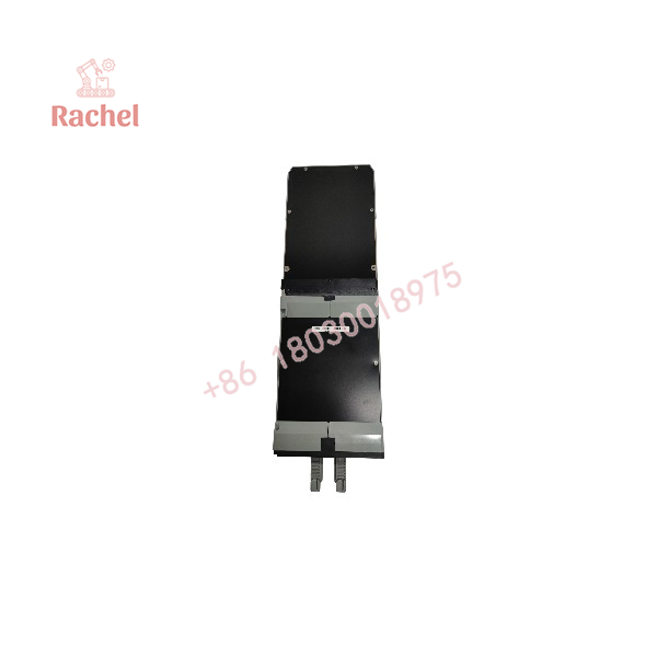
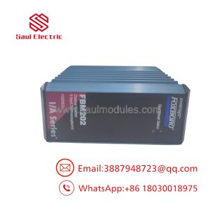
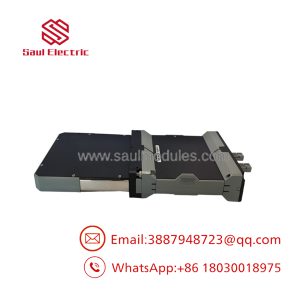
FBM07
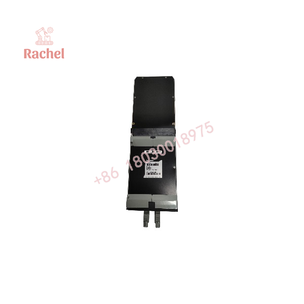
FBM07
Engineering Selection Highlights
- Select FBM07 when the application requires 16 channels of dry-contact or low-to-medium DC voltage discrete input on a 100 Series I/A Series Fieldbus segment.
- Confirm that the intended field signals match either the internal 24 V DC contact-sense characteristics or the 15–130 V DC voltage-monitor thresholds; higher AC voltages require a different FBM family.
- Plan for the optional FBM12 expansion module if more than 16 points are needed at the same Fieldbus node.
- Verify that the cabinet power supply provides a stable redundant 26–42 V DC feed within the module’s consumption limits (7 W main only).
- Ensure the chosen termination assembly type matches the plant wiring practice (compression, ring-lug, or discrete wire).
- Account for the 0–60 °C operating temperature range and 5–95 % non-condensing humidity when locating the module.
- Use the configurable 4–32 ms filter to match the expected contact bounce or noise environment of the field devices.
Dimensions, Mounting & Connection Notes
The FBM07 is a standard 100 Series Fieldbus Module form factor designed for plug-in mounting on an I/A Series baseplate or in a modular rack. Field wiring is terminated on a separate Termination Cable Assembly (TCA) or equivalent termination block that mates with the module. Three common termination styles are supported: direct connection block, plug connector block, and discrete wire block. No specific overall module dimensions or weight values beyond the standard 100 Series envelope are required for selection when the correct baseplate and TCA are used. Installation must respect the 0–60 °C operating temperature and non-condensing humidity limits. Orientation follows normal cabinet practices for 100 Series FBMs; adequate ventilation should be provided given the heat-dissipation figures.
System Compatibility & Integration Requirements
| Item / Dependency | Verified Compatibility or Requirement | Practical Note |
|---|---|---|
| System Family | Foxboro I/A Series DCS | 100 Series Fieldbus Module subsystem |
| Module Role | Expandable main FBM | Supports one FBM12 expansion module |
| Fieldbus | Redundant module Fieldbus | Communicates with associated FCM or control processor |
| Power Supply | Redundant 26–42 V DC | Shared with baseplate / cabinet supply |
| Termination | Compatible TCA / termination assembly | Direct-connection, plug-connector, or discrete-wire blocks |
| Expansion | FBM12 Contact/dc Expansion Input Module | Doubles channel count when installed |
| Software | I/A Series control software | Digital input, SOE, pulse-count, or ladder-logic application programs |
FAQ
What is the Foxboro FBM07?
The Foxboro FBM07 is a 16-channel Contact/dc Input Interface Module for the I/A Series system that monitors dry contacts or DC voltage signals and places the discrete states on the module Fieldbus.
Which system does the FBM07 belong to?
It belongs to the Foxboro I/A Series 100 Series Fieldbus Module family and communicates via the redundant module Fieldbus.
What signal types does the FBM07 accept?
Each of the 16 channels can be used either as a contact sensor (internal 24 V DC excitation) or as a DC voltage monitor (15–130 V DC on-state).
Can the channel count be increased?
Yes. One FBM12 Contact/dc Expansion Input Interface Module can be added to the FBM07 main module, providing an additional 16 channels.
What power supply does the FBM07 require?
A redundant 26–42 V DC supply. Maximum consumption is 7 W for the main module alone and 12 W when an expansion module is fitted.
What isolation is provided?
Each channel withstands 1250 V ac for one minute relative to earth (ground).
What filtering is available?
Input filter/debounce time is configurable at 4, 8, 16, or 32 ms.
What is the operating temperature range?
0 to 60 °C (32 to 140 °F) with 5 to 95 % relative humidity, non-condensing.
Verification & Troubleshooting Notes
- Confirm module identity by the FBM07 designation and part number (commonly P0400YH or CM400YH) on the label and by successful recognition on the I/A Series Fieldbus.
- Verify that the correct termination assembly is installed and that field wiring matches the chosen mode (contact-sense versus voltage-monitor).
- Check that the redundant 26–42 V DC power is present and within tolerance; power-related faults are reported through the Fieldbus diagnostics.
- Observe channel status LEDs (when present on the associated termination assembly) and compare against expected field device states.
- If intermittent or false transitions occur, review the configured filter time and the quality of field wiring/shielding.
- Module-level communication or power faults appear as Fieldbus diagnostics at the control processor; replace the module only after confirming power, Fieldbus integrity, and correct letterbug assignment.

 Start Chat


