





Description
Core Product Summary (Brand / Model / Key Attributes)
The Foxboro FBM14 is a Contact/dc Expansion Input/Output Interface Module for the Foxboro I/A Series distributed control system. It functions as the expansion counterpart to the FBM09 main module, adding discrete input and output capacity on the same Fieldbus node.
The module provides 8 independent input channels that can be used collectively for contact sensing or DC voltage monitoring, plus 8 independent output channels for DC switching with either an external or internal source. It connects to the Fieldbus through the supporting main module and shares the redundant 26–42 V DC power feed. When paired with an FBM09, the combined assembly supports 16 discrete I/O points while remaining within the documented power and thermal limits of the 100 Series subsystem.
Key Technical Specifications
| Parameter | Specification |
|---|---|
| Product Type | Contact/dc Expansion Input/Output Interface Module |
| Role | Expansion module (requires FBM09 main module) |
| Input Channels | 8 independent |
| Input Functions | Contact sensing or DC voltage monitoring (collective mode) |
| Output Channels | 8 independent |
| Output Functions | DC output switching with external source or internal source |
| Filter/Debounce Time | Configurable: 4, 8, 16, or 32 ms |
| Contact Sensor – Open-Circuit Voltage | 24 V dc ±10% |
| Contact Sensor – Short-Circuit Current | 2.5 mA maximum |
| Contact Sensor – ON-State Resistance | 1 kΩ maximum |
| Contact Sensor – OFF-State Resistance | 100 kΩ minimum |
| Voltage Monitor – ON-State Voltage | 15 to 130 V dc |
| Voltage Monitor – OFF-State Voltage | 0 to 5 V dc |
| Voltage Monitor – Current | 2.2 mA typical (5 to 130 V dc) |
| Output Switch (External Source) – Applied Voltage | 60 V dc maximum |
| Output Switch (External Source) – Load Current | 0.5 A maximum |
| Output Switch (External Source) – On-State Voltage Drop | 0.5 V typical at 0.5 A |
| Output Switch (External Source) – On-State Current Limit | 0.75 A typical |
| Output Switch (External Source) – Off-State Leakage | < 100 µA typical, 1.0 mA maximum |
| Output Switch (Internal Source) – Output Voltage (no load) | 11 V dc ±2 V dc |
| Output Switch (Internal Source) – Source Resistance | 660 Ω nominal |
| Power Input (Redundant, shared) | 26 to 42 V dc |
| Power Consumption (with main) | Main + expansion: 11 W maximum |
| Heat Dissipation (with main) | Main + expansion: 18 W maximum |
| Operating Temperature | 0 to 60 °C (32 to 140 °F) |
| Relative Humidity | 5 to 95 % (non-condensing) |
| Storage Temperature | –40 to +70 °C |
| System | Foxboro I/A Series (100 Series FBM subsystem) |
Detailed Product Overview
The Foxboro FBM14 expands the discrete I/O capacity of an FBM09 main module within the I/A Series 100 Series Fieldbus architecture. It does not connect independently to the Fieldbus; instead it is functionally dependent on the supporting main module, which handles communication and application-program execution for both units.
The eight input channels operate as a group in either contact-sense mode or voltage-monitor mode. In contact-sense mode the assembly supplies 24 V DC open-circuit excitation and detects contact closure. In voltage-monitor mode it senses the presence of an external DC voltage between the defined on-state and off-state thresholds. Configurable digital filtering (4–32 ms) reduces the effects of contact bounce and noise.
The eight output channels provide solid-state DC switching. When configured for external source, each channel can switch up to 60 V DC at 0.5 A continuous, with current limiting on short-circuit. When configured for internal source, the module supplies approximately 11 V DC through a nominal 660 Ω source resistance, suitable for driving solid-state relays or similar low-power loads. Inductive loads require an external protective diode.
Power and thermal loading are shared with the main module. The combined main-plus-expansion pair draws a maximum of 11 W and dissipates up to 18 W. Field wiring is terminated on the associated termination assembly that mates with the main/expansion pair. The module occupies a standard 100 Series expansion position and is intended for installation in the same environmental conditions specified for the family (0–60 °C operating, non-condensing humidity).
Application programs running in the main module treat the expansion channels as an extension of the main module’s I/O map, supporting digital I/O, sequence-of-events, or simple ladder-logic functions as configured in the I/A Series control software.
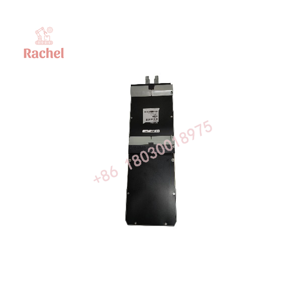
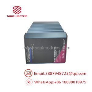
FBM14
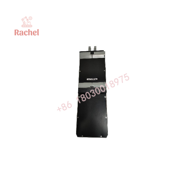
FBM14
System Compatibility & Integration Requirements
| Item / Dependency | Verified Compatibility or Requirement | Practical Note |
|---|---|---|
| System Family | Foxboro I/A Series DCS | 100 Series Fieldbus Module subsystem |
| Required Main Module | FBM09 Contact/dc Input/Output Interface Module | FBM14 is functionally dependent on the main |
| Fieldbus Connection | Via the supporting main module | Does not connect independently to the Fieldbus |
| Power Supply | Redundant 26–42 V DC (shared) | Combined consumption with main: 11 W max |
| Termination | Compatible TCA / termination assembly for the main/expansion pair | Direct-connection, plug-connector, or discrete-wire blocks |
| Channel Capacity (paired) | 8 DI + 8 DO from expansion + 8 DI + 8 DO from main | Total 16 discrete I/O points |
| Software | I/A Series control software | Application programs execute in the main module |
Dimensions, Mounting & Connection Notes
The FBM14 is a standard 100 Series expansion Fieldbus Module designed to mount adjacent to its supporting FBM09 main module on the same baseplate or in the same modular rack position. Field wiring is brought to a common termination assembly that serves both the main and expansion modules. Three common termination styles are supported: direct connection block, plug connector block, and discrete wire block. Installation follows normal 100 Series practices; adequate ventilation must be provided for the combined heat dissipation of the pair. Orientation and clearances are those specified for the 100 Series FBM family. The module is intended for indoor cabinet mounting within the stated temperature and humidity limits.
Engineering Selection Highlights
- Select FBM14 only when expanding an existing or planned FBM09 main module; the expansion module cannot operate standalone.
- Confirm that the required I/O mix is 8 discrete inputs plus 8 discrete outputs and that signal levels match the contact-sense / voltage-monitor and 60 V DC / 0.5 A switching ratings.
- Verify that the cabinet power supply and thermal design can accommodate the combined 11 W consumption and 18 W dissipation of the main-plus-expansion pair.
- Match the termination assembly style (direct-connection, plug-connector, or discrete-wire) to the plant wiring standard.
- Use the configurable filter time to suit the expected contact bounce or electrical noise environment.
- For inductive loads on the outputs, plan for customer-supplied protective diodes rated for the load current and at least 1.3 times the supply voltage.
- Ensure the installation remains within the 0–60 °C operating temperature and 5–95 % non-condensing humidity limits.
FAQ
What is the Foxboro FBM14?
The Foxboro FBM14 is a Contact/dc Expansion Input/Output Interface Module that adds 8 discrete inputs and 8 discrete outputs when paired with an FBM09 main module in the I/A Series system.
Can the FBM14 operate by itself?
No. It is an expansion module and must be used with a supporting FBM09 main module that provides the Fieldbus connection and application processing.
What input signal types does the FBM14 support?
The eight input channels can be used as a group for either contact sensing (internal 24 V DC excitation) or DC voltage monitoring (15–130 V DC on-state).
What output capabilities does the FBM14 provide?
Eight solid-state DC output channels that can switch an external source up to 60 V DC at 0.5 A, or supply an internal approximately 11 V DC source for low-power loads.
What power supply is required?
A redundant 26–42 V DC supply shared with the main module. Combined consumption of the main-plus-expansion pair is 11 W maximum.
What is the operating temperature range?
0 to 60 °C (32 to 140 °F) with 5 to 95 % relative humidity, non-condensing.
Are protective diodes required for outputs?
Yes, for inductive loads when using the external-source output configuration. The diode must handle the maximum load current and be rated greater than 1.3 times the supply voltage.
Verification & Troubleshooting Notes
- Confirm that the FBM14 is installed with a compatible FBM09 main module and that both are recognized on the Fieldbus.
- Verify correct mode configuration (contact-sense versus voltage-monitor for inputs; external versus internal source for outputs) at the termination assembly and in the control software.
- Check that the shared 26–42 V DC power is present and within tolerance; power or communication faults are reported through the main module’s diagnostics.
- Observe channel status indicators on the termination assembly and compare against expected field device states.
- For intermittent input transitions, review the configured filter time and field-wiring quality.
- For output problems, confirm load current is within 0.5 A, check for proper protective diodes on inductive loads, and verify that the output configuration matches the intended source type.
- Module replacement should be performed only after confirming power, Fieldbus integrity, and correct assignment of the main/expansion pair.

 Start Chat


