





Description
Core Product Summary
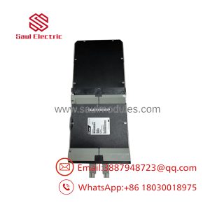
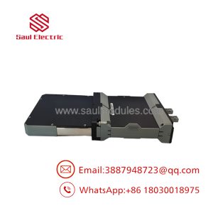
The FOXBORO FBM201 is an eight-channel analog input interface module used in Foxboro I/A Series and related Foxboro DCS architectures. The standard FBM201 accepts 0–20 mA DC signals from analog transmitters and other compatible current sources, converting them into digital measurement values for the control system.
Each channel is galvanically isolated from the other channels and ground. The module uses independent sigma-delta analog-to-digital conversion and configurable integration settings to support process measurement and noise filtering. It communicates with an associated Fieldbus Communication Module (FCM) or Field Control Processor (FCP) through the redundant 2 Mbps module Fieldbus.
The standard FBM201 is commonly associated with hardware part number P0914SQ, superseded in some documentation by RH914SQ. Confirm the complete part number and hardware type before ordering, as the standard FBM201, its voltage-input variants, and the Compact FBM201 have different specifications and mounting requirements.
Key Technical Specifications
| Parameter | Specification |
|---|---|
| Manufacturer | Foxboro / Schneider Electric |
| Model | FBM201 |
| Product family | I/A Series / Foxboro DCS 200 Series |
| Product type | Analog Input Interface Module |
| Number of channels | 8 |
| Standard input range | 0–20 mA DC |
| Input configuration | Two-wire DC input from analog sensors |
| Channel isolation | Galvanically isolated channel-to-channel and channel-to-ground |
| A/D conversion | Independent sigma-delta converter per channel |
| Analog accuracy, including linearity | ±0.03% of span |
| Accuracy temperature coefficient | ±50 ppm/°C |
| Nominal input impedance | 61.5 Ω |
| Common-mode rejection | Greater than 100 dB at 50/60 Hz |
| Normal-mode rejection | Greater than 95 dB at 50/60 Hz |
| Fieldbus communication | Redundant 2 Mbps module Fieldbus |
| Redundant input power | 24 V DC, +5% / −10% |
| Power consumption | 7 W |
| Maximum heat dissipation | 3 W |
| Operating temperature | −20 to +70°C |
| Storage temperature | −40 to +70°C |
| Relative humidity | 5–95%, noncondensing |
| Environmental classification | Class G3, harsh environments |
| Approximate dimensions | 102 × 45 × 104 mm |
| Height with mounting lugs | 114 mm |
| Approximate module weight | 284 g |
| Common hardware part number | P0914SQ / RH914SQ, depending on revision |
Model distinction: FBM201 is the standard 0–20 mA current-input version. FBM201b accepts 0–100 mV DC, FBM201c accepts 0–5 V DC, and FBM201d accepts 0–10 V DC. These variants are not interchangeable without verifying the signal type and system configuration.
The dimensions and weight above apply to the standard 200 Series module, not the separately specified Compact FBM201.
Engineering Selection Highlights
Eight isolated analog input channels
The FBM201 provides eight independent analog inputs. Galvanic isolation between channels and ground helps limit the effects of ground-potential differences and electrical interference in multi-transmitter installations.
Sigma-delta signal conversion
Each input channel uses an independent sigma-delta converter. This architecture supports accurate conversion of analog process signals into digital values for the DCS.
Configurable integration period
The analog-input application supports software-configurable integration settings. The controller receives averaged measurement values, allowing engineers to balance signal filtering against measurement response time.
Redundant Fieldbus communication
The FBM201 communicates through the redundant 2 Mbps module Fieldbus. It can communicate over either Fieldbus path, allowing continued communication over the active path if the other path becomes unavailable or is switched at system level.
Flexible transmitter termination
Compatible termination assemblies support local or remote field wiring and arrangements for internally or externally loop-powered transmitters. The termination assembly must match the module and the field-circuit design.
HART electrical compatibility
The standard FBM201 is electrically compatible with standard HART signals. This should not be interpreted as confirmation that every HART configuration or asset-management function is supported; verify the required functionality against the installed DCS architecture.
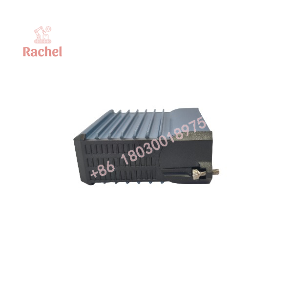
FBM201
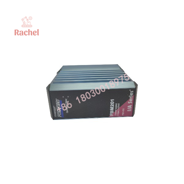
FBM201
System Compatibility & Integration Requirements
| Compatibility item | Engineering check |
|---|---|
| Control-system platform | Confirm the installed Foxboro I/A Series or compatible Foxboro DCS architecture. |
| Module identity | Verify FBM201 and the complete hardware part number, such as P0914SQ or RH914SQ. |
| Input signal | Confirm that the field instrument provides a compatible 0–20 mA DC signal. |
| Transmitter power | Check whether the transmitter is internally or externally loop-powered. |
| Termination assembly | Verify the approved TA and termination cable for the installed module. |
| Fieldbus interface | Confirm connection to the associated FCM or FCP and the redundant 2 Mbps Fieldbus. |
| Power supply | Confirm the redundant 24 V DC input supply is within specification. |
| Baseplate | Verify the standard 200 Series baseplate and mounting arrangement. |
| Channel configuration | Check channel scaling, integration settings, and rate-of-change limits. |
| Replacement validation | Compare wiring, part number, channel mapping, and actual input readings before returning the loop to service. |
The standard FBM201 is not a universal analog input card. A voltage-input variant or a Compact FBM201 should not be substituted based only on a similar model name or physical appearance.
Dimensions, Mounting & Connection Notes
The standard FBM201 uses a modular baseplate that accommodates four or eight fieldbus modules. The baseplate can be DIN-rail mounted or rack mounted and provides connections for Fieldbus, redundant DC power, and termination cables.
Standard module dimensions
- Height: 102 mm
- Height with mounting lugs: 114 mm
- Width: 45 mm
- Depth: 104 mm
- Approximate weight: 284 g
Field I/O signals connect through compatible termination assemblies. These assemblies are available in different wiring arrangements, including compression and ring-lug connections. The appropriate termination hardware depends on the installation and the field-circuit design.
Before installation:
- Verify the full module and termination assembly part numbers.
- Confirm the field wiring and loop-power arrangement.
- Inspect connectors and mounting hardware for damage or corrosion.
- Check that the module is installed in the correct baseplate type.
- Follow the approved isolation and module-replacement procedure for the plant.
Foxboro documentation indicates that the module can be removed and replaced without removing field-device termination cabling, power cabling, or communications cabling. Whether replacement can be performed with the system energized must be determined from the site-specific procedure and system design.
Detailed Product Overview
Analog signal acquisition
The standard FBM201 accepts eight analog current inputs in the 0–20 mA DC range. This encompasses the commonly used 4–20 mA instrument signal, provided the transmitter and input loop are configured correctly.
The module performs the conversion required to pass field measurements to the associated control processor. Engineers should verify signal scaling in the DCS database as well as the physical input wiring. Incorrect scaling can produce inaccurate displayed values even when the hardware is operating normally.
Channel isolation and measurement quality
Each channel is galvanically isolated from the other channels and from ground. The specified isolation withstand capability is 600 VAC for one minute between a channel and ground, or between one channel and another.
This is a withstand-test rating, not permission to connect the input channels permanently to hazardous voltages. Field signals must remain within their published operating limits.
The module’s stated analog accuracy, including linearity, is ±0.03% of span, with an accuracy temperature coefficient of ±50 ppm/°C. Overall loop accuracy also depends on transmitter performance, wiring, calibration of the complete measurement chain, and the engineering configuration.
Conversion timing and noise filtering
The module uses an independent sigma-delta converter for each channel. Foxboro documentation states that a new analog reading can be available every 25 ms, with configurable integration periods used to average readings and reduce process or electromagnetic noise.
The integration setting affects the behavior of the measurement signal. Longer averaging can reduce fluctuations but may also slow the response to rapid process changes. Select the setting according to the control-loop response requirements and the characteristics of the instrument signal.
Fieldbus and power architecture
The FBM201 communicates with an associated FCM or FCP through the redundant 2 Mbps module Fieldbus. Communication can continue over the active path if the other path is unsuccessful or switched at system level.
The module uses a redundant 24 V DC supply with a specified tolerance of +5% / −10%. Its documented power consumption is 7 W, with maximum heat dissipation of 3 W. Cabinet power capacity, thermal loading, and Fieldbus configuration should be checked during replacement planning.
Termination assemblies and loop power
The field instruments connect through termination assemblies and cables compatible with the FBM201 subsystem. Available arrangements accommodate different field-wiring and transmitter-power configurations.
When troubleshooting a failed channel, check the transmitter output, loop supply, wiring continuity, termination assembly, and DCS channel configuration before concluding that the module itself is defective.
Replacement and hardware identification
The standard FBM201 is commonly identified by P0914SQ, with RH914SQ appearing as a superseding part number in product listings. Always use the exact marking on the installed unit and compare it with the applicable documentation.
The Compact FBM201 is a separate hardware configuration. Its compact enclosure, mounting baseplate, dimensions, and associated termination hardware differ from the standard 200 Series module. Do not assume that it is a direct mechanical replacement for a standard FBM201.
Applications & System Role
The FBM201 provides analog measurement acquisition between field instrumentation and a Foxboro distributed control system.
Typical application areas include:
- Process instrumentation: Acquiring compatible current signals from pressure, flow, level, and other transmitters.
- Chemical and petrochemical plants: Feeding analog process measurements into DCS control and monitoring functions.
- Power generation: Collecting compatible instrument signals for plant monitoring and control.
- Water and wastewater treatment: Interfacing analog measurement loops with process-control logic.
- Manufacturing systems: Bringing transmitter measurements into centralized process monitoring.
- Legacy DCS maintenance: Replacing a failed FBM201 while retaining the existing I/O architecture and field wiring.
The specific application depends on the connected transmitter, loop-power arrangement, configured engineering range, and control-system design.
Frequently Asked Questions
Q1. What is the FOXBORO FBM201?
It is an eight-channel analog input interface module for Foxboro I/A Series and compatible Foxboro DCS installations. The standard version accepts 0–20 mA DC signals.
Q2. How many input channels does the FBM201 have?
The module provides eight isolated and independent analog input channels.
Q3. Can the FBM201 accept 4–20 mA signals?
Yes. A 4–20 mA signal falls within the standard FBM201’s 0–20 mA DC input range, provided the loop wiring and DCS scaling are configured correctly.
Q4. What is the accuracy of the FBM201?
Foxboro specifies analog accuracy, including linearity, of ±0.03% of span, with a temperature coefficient of ±50 ppm/°C.
Q5. What power supply does the FBM201 require?
The standard module’s redundant input power specification is 24 V DC, +5% / −10%. Power consumption is listed as 7 W.
Q6. What is the difference between FBM201, FBM201b, FBM201c, and FBM201d?
The standard FBM201 accepts 0–20 mA DC. FBM201b accepts 0–100 mV DC, FBM201c accepts 0–5 V DC, and FBM201d accepts 0–10 V DC. They serve different input-signal requirements.
Q7. Is the FBM201 compatible with HART transmitters?
The standard FBM201 is electrically compatible with standard HART signals. Confirm the required HART communication and asset-management functions against the specific DCS configuration.
Q8. What should be checked before ordering a replacement?
Confirm the full model and part number, standard versus Compact hardware, input signal range, termination assembly, baseplate, loop-power arrangement, and control-system configuration. After installation, verify each channel against a known input or calibrated signal source before returning the process loop to service.

 Start Chat


