





Description
Key Technical Specifications
| Parameter | Specification |
|---|---|
| Manufacturer | Foxboro / Schneider Electric |
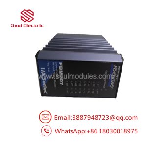
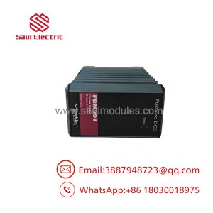
| Model | FBM203 |
| Product family | Foxboro DCS / I/A Series |
| Product type | RTD analog input interface module |
| Number of channels | 8 |
| Input resistance range | 0–320 Ω per channel |
| Supported RTD wiring | 2-wire or 3-wire |
| Typical sensor types | Platinum and nickel RTDs |
| Nominal platinum resistance | 100 Ω at 0°C |
| Nominal nickel resistance | 235 Ω at 0°C |
| Nominal sensor current | 0.19 mA DC |
| Maximum lead resistance | 50 Ω per lead |
| Analog accuracy, including linearity | ±0.03% of span |
| Accuracy temperature coefficient | ±50 ppm/°C |
| Common-mode rejection | Greater than 125 dB at 50/60 Hz |
| Normal-mode rejection | Greater than 95 dB at 50/60 Hz |
| A/D conversion | Independent sigma-delta converter per channel |
| New input value rate | Every 25 ms |
| Integration period | Software configurable |
| Communication | Redundant 2 Mbps module Fieldbus |
| Compatible controller interface | Associated FCM or FCP |
| Input power | Redundant 24 V DC, +5% / −10% |
| Maximum power consumption | 3 W |
| Maximum heat dissipation | 3 W |
| Operating temperature | −20 to +70°C |
| Storage temperature | −40 to +70°C |
| Relative humidity | 5–95%, noncondensing |
| Environmental classification | ISA S71.04 Class G3 |
| Approximate module weight | 284 g |
| Dimensions (H × W × D) | 102 × 45 × 104 mm |
| Height including mounting lugs | 114 mm |
| Current published part number | RH914SV |
| Common legacy ordering number | P0914SV |
These specifications apply to the standard FBM203. The manufacturer identifies different input ranges and wiring arrangements for FBM203b, FBM203c, and FBM203d.
Engineering Selection Highlights
Eight isolated RTD inputs
The FBM203 provides eight independent temperature-measurement channels. Each channel is galvanically isolated from the other channels and ground, helping limit the effects of ground-potential differences in multi-sensor installations.
Platinum and nickel sensor support
The standard FBM203 supports compatible platinum and nickel RTDs within its 0–320 Ω input range. Sensor type and resistance curve must be configured correctly in the control system to produce valid engineering-unit readings.
Sigma-delta conversion
Each channel uses its own sigma-delta converter. The module can provide a new analog input value every 25 ms, with software-configurable integration to average readings and reduce process noise and power-line interference.
Redundant Fieldbus architecture
The FBM203 communicates with its associated Fieldbus Communication Module (FCM) or Field Control Processor (FCP) over the redundant 2 Mbps module Fieldbus. It can continue communicating through the active path if the other path becomes unavailable or is switched at system level.
Flexible termination arrangements
The module supports DIN-rail-mounted termination assemblies. The standard FBM203 also supports a baseplate-mounted termination arrangement for paired FBM203/b/c modules in specified 200 Series baseplate positions. The chosen termination hardware must match the installed module and wiring design.
paresource.schneider-electric.com
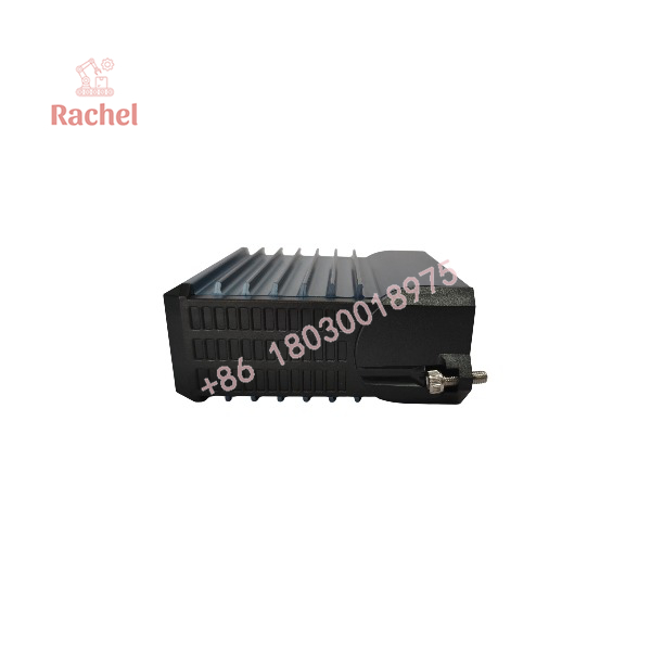
FBM203
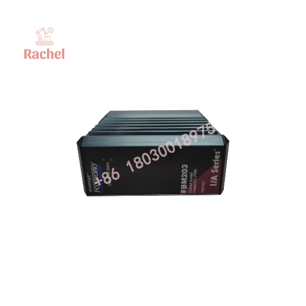
FBM203
System Compatibility & Integration Requirements
| Compatibility item | What to verify |
|---|---|
| Control platform | Confirm the installed Foxboro DCS or I/A Series architecture supports the FBM203. |
| Module variant | Verify the exact designation: FBM203, FBM203b, FBM203c, or FBM203d. |
| Sensor resistance | Confirm the connected RTD remains within the applicable input range. |
| RTD wiring | Match 2-wire or 3-wire wiring to the standard FBM203; the FBM203d is designed for 4-wire input. |
| Sensor type | Verify platinum or nickel RTD type and the correct resistance-temperature curve. |
| Termination assembly | Match the TA part number, cable type, and connector arrangement. |
| Fieldbus | Confirm connection to the associated FCM/FCP and redundant 2 Mbps Fieldbus. |
| Power supply | Verify the redundant 24 V DC supply and its tolerance. |
| Baseplate | Confirm the standard 200 Series baseplate or approved conversion mounting structure. |
| Channel configuration | Check sensor type, scaling, integration period, and rate-of-change limits. |
| Commissioning | Compare measured values against a reference temperature or resistance input. |
The FBM203 should not be substituted for another RTD variant solely because the modules share a family name. The input resistance range, sensor wiring, and termination arrangement determine compatibility.
Dimensions, Mounting & Connection Notes
The standard module measures approximately 102 × 45 × 104 mm, with a height of 114 mm including mounting lugs. Its approximate weight is 284 g.
The FBM203 mounts on a modular baseplate that accommodates four or eight Fieldbus Modules. The baseplate can be installed horizontally or vertically on a DIN rail, or horizontally in a 19-inch rack with the appropriate mounting kit. The module can also be installed on an approved 100 Series conversion mounting structure.
paresource.schneider-electric.com
Termination options include:
- DIN-rail-mounted compression-screw termination assemblies.
- DIN-rail-mounted ring-lug termination assemblies.
- Baseplate-mounted compression-screw termination assemblies for supported FBM203/b/c configurations.
The current published specification identifies the following hardware numbers:
| Component | Part number |
|---|---|
| FBM203 module | RH914SV |
| DIN-rail compression-screw TA | RH916XJ |
| Baseplate-mounted compression-screw TA | RH924WN |
| Ring-lug TA | P0917JM |
Confirm the exact assembly and cable against the installed configuration before ordering. These part numbers are documented for the current specification and should not be assumed to cover every legacy hardware revision.
Detailed Product Overview
RTD signal acquisition
The FBM203 measures resistance from compatible temperature sensors and converts the input into digital values for the associated controller. The standard module accepts 2-wire or 3-wire RTD inputs across a 0–320 Ω range.
The documented typical sensors include 100 Ω platinum RTDs at 0°C and 235 Ω nickel RTDs at 0°C. The actual temperature calculation depends on the sensor’s resistance curve and the control-system configuration.
Two-wire measurements do not compensate for lead resistance or changes in lead resistance with temperature. For installations where lead resistance affects measurement accuracy, select the wiring arrangement according to the sensor and system requirements.
Measurement accuracy and noise rejection
The standard FBM203 has a specified analog accuracy, including linearity, of ±0.03% of span. Its temperature coefficient is ±50 ppm/°C. The module also specifies common-mode rejection greater than 125 dB and normal-mode rejection greater than 95 dB at 50/60 Hz.
These figures describe module performance under the manufacturer’s stated conditions. Overall measurement accuracy also depends on the sensor, lead wiring, installation conditions, and configured engineering range.
Integration and response behavior
Each channel uses an independent sigma-delta converter and can produce a new input value every 25 ms. The integration period is configurable in software.
A longer integration period averages more readings, which can improve stability when electrical or process noise is present. However, it can also slow the response to rapid temperature changes. Configure the period according to the measurement dynamics and control-loop requirements.
Fieldbus communication and power
The FBM203 communicates with an associated FCM or FCP through the redundant 2 Mbps module Fieldbus. It can use either Fieldbus path, allowing communication over the active path if the other path fails or is switched.
The module uses a redundant 24 V DC input supply with a tolerance of +5% / −10%. Maximum power consumption and heat dissipation are each specified at 3 W. Verify cabinet power capacity and environmental conditions when planning a replacement or adding a module.
Termination assemblies and field wiring
Termination assemblies provide the interface between the RTD wiring and the module subsystem. The manufacturer documents DIN-rail-mounted assemblies and a baseplate-mounted option for supported FBM203/b/c arrangements.
Cable length, connector type, and terminal construction should be matched to the existing installation. Before replacement, inspect the module and termination connectors, verify sensor wiring, and confirm the installed sensor type and configuration in the DCS.
Replacement and maintenance considerations
The current manufacturer specification identifies RH914SV as the FBM203 module part number, while P0914SV appears in legacy and supplier records. When sourcing a replacement, compare the complete hardware identification with the installed module and the system’s approved parts documentation.
After installation, check Fieldbus communication, verify every configured RTD channel, and compare the DCS reading with a known resistance input or calibrated temperature reference. Investigate wiring, sensor, termination, and configuration errors before attributing an incorrect reading to a defective module.
Applications & System Role
The FBM203 is intended for industrial process applications that require resistance-based temperature measurements to be collected by a distributed control system.
Typical application areas include:
- Chemical processing: Monitoring vessel, line, and equipment temperatures using compatible RTDs.
- Petrochemical facilities: Acquiring process-temperature measurements for monitoring and control.
- Power generation: Measuring temperatures in auxiliary systems and compatible plant equipment.
- Industrial manufacturing: Monitoring temperature in production machinery and process equipment.
- Plant instrumentation: Integrating platinum and nickel RTD sensors with a Foxboro DCS.
- Legacy DCS maintenance: Replacing an installed RTD module while retaining the established I/O and termination architecture.
The FBM203 is an input interface module. It acquires and converts sensor signals for the control system; it does not independently perform the complete temperature-control function.
Frequently Asked Questions
Q1. What is the FOXBORO FBM203?
It is an eight-channel RTD input module used with Foxboro DCS and I/A Series systems.
Q2. What is the input range of the standard FBM203?
The standard FBM203 accepts RTD resistance inputs from 0 to 320 Ω per channel.
Q3. Which RTD sensors can it support?
The manufacturer’s specification lists platinum and nickel RTDs, including typical 100 Ω platinum and 235 Ω nickel sensors at 0°C, subject to the sensor curve and system configuration.
Q4. Does the FBM203 support 3-wire RTDs?
Yes. The standard FBM203 supports 2-wire and 3-wire RTD inputs. The FBM203d is the designated 4-wire RTD variant.
Q5. What is the module’s specified accuracy?
The standard FBM203 has an analog accuracy specification, including linearity, of ±0.03% of span and a temperature coefficient of ±50 ppm/°C.
Q6. What power supply does the FBM203 require?
It requires a redundant 24 V DC input supply with a specified tolerance of +5% / −10%. Maximum power consumption is 3 W.
Q7. What is the difference between FBM203 and FBM203b/c/d?
The standard FBM203 accepts 0–320 Ω RTD inputs with 2-wire or 3-wire wiring. FBM203b supports 0–640 Ω, FBM203c supports 0–30 Ω, and FBM203d supports 4-wire RTD inputs within a 0–320 Ω range.
Q8. Which part number should I use when ordering?
The current manufacturer specification identifies the FBM203 as RH914SV. P0914SV also appears in legacy supplier records. Verify the installed unit’s label and approved parts list before placing an order.
Q9. Does the FBM203 require calibration?
The manufacturer’s specification states that calibration of the module and termination assembly is not required. Sensor verification and loop checks may still be necessary under the site’s maintenance procedures.
Q10. What should be checked before replacing an FBM203?
Confirm the module variant, part number, RTD type, wiring arrangement, termination assembly, baseplate, Fieldbus configuration, and channel scaling. Validate readings against a known resistance or temperature reference before returning the measurement loop to service.

 Start Chat


