





Description
Core Product Summary
The FOXBORO FBM218 is a Compact 200 Series HART communication redundant output interface module designed to deliver analog output signals to compatible field instruments and control devices. It provides eight individually isolated output channels. Each channel can supply a standard 4–20 mA analog signal or a 4–20 mA signal with a superimposed HART digital communication signal.
The module includes a dedicated FSK modem for each channel, enabling bidirectional digital communication with compatible HART field devices. Supported functions include HART universal, common-practice, and device-specific commands. HART Versions 5, 6, and 7 are supported, with a documented communication rate of two messages per second. Burst communication mode is not supported.
The FBM218 can operate as part of a redundant module pair. In this arrangement, one module acts as the master and the other as the tracker, with field output signals connected through a common termination assembly and the specified redundant adapter.
Part-number distinction: P0917XV is not the FBM218 module’s own part number. Schneider Electric’s current product specification lists RH101AE as the Compact FBM218 module part number and RH926SP as the compression termination assembly superseding P0926SP and P0917XV.
Key Technical Specifications
FBM218 module
| Parameter | Manufacturer specification |
|---|---|
| Manufacturer | Foxboro / Schneider Electric |
| Module model | Compact FBM218 |
| Module part number | RH101AE |
| Product type | HART communication redundant analog output interface |
| Number of output channels | 8 |
| Output signal | 4–20 mA analog, with or without superimposed HART |
| HART versions | 5, 6, and 7 |
| HART communication | Point-to-point, master/slave, asynchronous, half-duplex |
| HART communication speed | 1,200 baud |
| HART message rate | 2 messages per second |
| Analog output accuracy, including linearity | ±0.05% of span between 4 and 20 mA |
| Resolution | 13 bits |
| Maximum output load | 750 Ω |
| Maximum rate of change | 20 mA in 60 ms |
| Channel isolation | Galvanic isolation between channels, ground, and module logic |
| Redundancy | Supported with a paired module and RH101AY redundant adapter |
| Module Fieldbus | Redundant 2 Mbps HDLC |
| Supply voltage | 24 VDC, +5%/−10% |
| Maximum power consumption | 8 W |
| Maximum heat dissipation | 4 W |
| Operating temperature | −20 to +60°C |
| Storage temperature | −40 to +70°C |
| Relative humidity | 5–95%, noncondensing |
| Operating altitude | −300 to +3,000 m |
| Storage altitude | −300 to +12,000 m |
| Vibration | 0.75 g from 5 to 500 Hz |
| Environmental classification | ISA S71.04 Class G3 |
| Calibration | Module and termination assembly calibration not required |
P0917XV termination assembly
| Parameter | Specification |
|---|---|
| Part number supplied | P0917XV |
| Associated module family | FBM215 / |
| Function | Field wiring termination for HART analog output channels |
| Manufacturer-listed superseding part number | RH926SP |
| Termination style | Compression terminals |
| Mounting | DIN rail |
| Termination cable length | Up to 30 m, depending on cable selection |
| Baseplate-side cable connector | 37-pin D-subminiature |
| Termination-assembly-side connector | 25-pin D-subminiature |
| Termination assembly material | Polyamide |
| Approximate termination assembly weight | 181 g for compression type |
Important: The module and termination assembly are separate components. Verify which item is required before placing an order.
Engineering Selection Highlights
Eight isolated analog outputs
The FBM218 supplies eight 4–20 mA output channels for compatible field devices. Individual channel isolation helps separate output circuits electrically and reduces direct interaction between field loops.
HART digital communication
Each output channel includes a dedicated FSK modem for HART communication. This allows the Foxboro control system to exchange supported digital commands with compatible field devices while maintaining the analog output signal.
The documented communication rate is two messages per second. Applications that depend on HART burst mode require a different approach.
Redundant module architecture
Two FBM218 modules can be configured as a redundant pair. The pair uses a master/tracker arrangement and a redundant adapter, RH101AY, to connect the pair to the shared termination assembly.
When the system detects a qualifying module failure, the failed module’s output is driven to 0 mA, allowing the corresponding channel in the functioning module to continue supplying the required loop current. This behavior depends on the configured redundancy and fail-safe settings.
Current-limited output design
Each channel is galvanically isolated, current-limited, and voltage-regulated. The module is designed to supply constant current into loads up to 750 Ω. Correct loop design must account for the connected instrument’s input requirements and wiring resistance.
Compact 200 Series installation
The Compact FBM218 mounts on a Compact 200 Series baseplate. Its associated termination assembly mounts on a DIN rail and connects to the module through a removable termination cable.
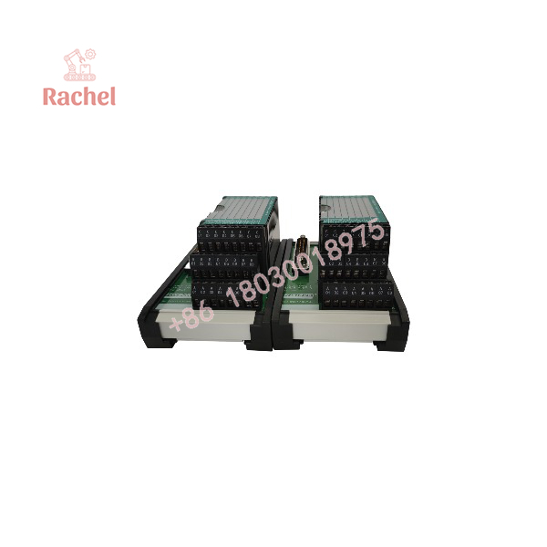
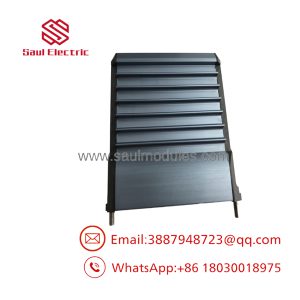
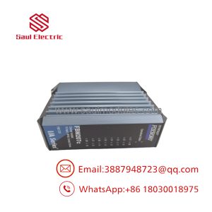
FBM218 P0917XV
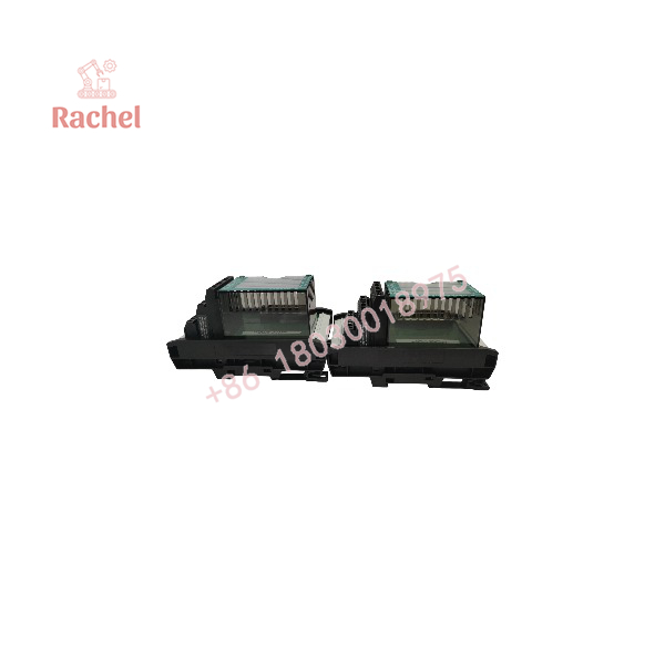
FBM218 P0917XV
System Compatibility and Integration Requirements
Control-system integration
Before installing an FBM218, confirm that the control processor, Compact 200 Series baseplate, software release, Fieldbus architecture, and redundancy arrangement support the module.
The module communicates with its associated Fieldbus Communication Module (FCM) or Field Control Processor (FCP) over the redundant 2 Mbps HDLC Fieldbus. It accepts communication over either Fieldbus path A or B.
Field-device compatibility
The module supports compatible 4–20 mA analog devices and HART instruments conforming to HART Versions 5, 6, or 7. Confirm the field device’s required output behavior, HART communication requirements, and load characteristics before commissioning.
Redundant configuration
For module-level redundancy:
- Install the two modules in adjacent baseplate positions.
- Follow the manufacturer’s prescribed slot arrangement.
- Use the RH101AY redundant adapter.
- Connect the shared termination cable and termination assembly as specified.
- Verify the master/tracker roles and fail-safe configuration in the control system.
Redundancy is a system configuration, not a feature that can be achieved by installing a single FBM218 alone.
Termination assembly selection
The manufacturer lists RH926SP as the compression-type termination assembly superseding P0926SP and P0917XV. Confirm that the replacement is appropriate for the installed wiring, certification requirements, cable type, and hardware revision.
Dimensions, Mounting, and Connection Notes
Module installation
The Compact FBM218 mounts on a Compact 200 Series 16-slot horizontal baseplate. The baseplate can be installed on a horizontal DIN rail or in a 19-inch rack using the applicable mounting kit.
The manufacturer’s specification gives the following mechanical details for the module:
| Parameter | Specification |
|---|---|
| Approximate module weight | 185 g |
| Mounting platform | Compact 200 Series 16-slot horizontal baseplate |
| Module part number | RH101AE |
| Redundant adapter | RH101AY |
Termination assembly and cabling
The associated termination assembly is mounted on a DIN rail. Available termination cables use polyurethane or low-smoke, zero-halogen (LSZH) construction, with lengths up to 30 m.
The cable connects to the baseplate through a 37-pin D-subminiature connector and to the termination assembly through a 25-pin D-subminiature connector.
For the compression termination assembly, the manufacturer specifies the following conductor sizes:
- Solid conductors: 0.2–4 mm²
- Stranded conductors: 0.2–2.5 mm²
- AWG: 24–12
- Stranded conductors with ferrules: 0.2–2.5 mm²
Use the termination assembly’s installation instructions for conductor preparation, terminal tightening, and wiring identification.
Installation checks
- Confirm whether the order is for FBM218 module RH101AE or termination assembly P0917XV/RH926SP.
- Check the installed baseplate and controller compatibility.
- Verify the termination cable and its connector arrangement.
- Confirm output loop resistance and connected device requirements.
- For redundant operation, verify the adjacent-slot arrangement and RH101AY adapter.
- Check the configured output fail-safe behavior before returning the control loop to service.
- Test analog output accuracy and HART communication according to the site’s commissioning procedure.
The module’s 600 VAC isolation withstand rating is a test rating, not an allowable continuous field voltage.
Detailed Product Overview
Analog output operation
The FBM218 receives output commands from the Foxboro control system and generates the corresponding analog current on the selected channel. Each channel can drive a compatible load up to the specified maximum of 750 Ω.
The module’s specified accuracy is ±0.05% of span between 4 and 20 mA, with 13-bit resolution. These values are useful for evaluating output performance, but final loop accuracy also depends on the receiving instrument, wiring, grounding, and system configuration.
HART communication operation
HART communication superimposes a digital FSK signal on the analog current loop. The FBM218 has a dedicated FSK modem per output channel, allowing supported digital communication with the connected HART instrument.
The system supports universal, common-practice, and device-specific commands, subject to the instrument and control-system software. It supports two messages per second and does not support burst communication mode.
Redundancy and fail-safe behavior
In a redundant pair, one module operates as the master and the other as the tracker. The outputs are combined in series through the redundant adapter. If a supported failure is detected in one module, its output is driven to 0 mA, while the corresponding channel of the functioning module continues supplying the required loop current.
The control-system configuration includes options for fail-safe action, fallback data, Fieldbus fail-safe enable, and delay time. These parameters should be checked during commissioning and before replacing a module.
Identifying the correct replacement part
P0917XV is identified by the manufacturer as a termination assembly used with FBM215/FBM218 systems. RH926SP is the listed superseding termination assembly part number. RH101AE is the Compact FBM218 module part number, while RH101AY is the redundant adapter.
For procurement, identify the exact component required and confirm whether the existing installation needs a module, a termination assembly, a redundant adapter, a termination cable, or a complete set.
Applications and System Role
The FBM218 is used where a Foxboro DCS must drive analog field-device loops while supporting HART communication.
Typical applications include:
- Control valve positioning: Supply 4–20 mA commands to compatible valve positioners.
- Variable-speed equipment interfaces: Provide analog reference signals to supported drive interfaces.
- Process control loops: Generate analog outputs for pressure, flow, temperature, or level control elements.
- Smart instrument integration: Communicate with compatible HART field devices using supported digital commands.
- Process skid control: Provide multiple analog output channels through a Compact 200 Series I/O architecture.
- Redundant output systems: Maintain output-loop operation through a supported master/tracker module arrangement.
The module supplies output signals and provides the communication interface. The control application determines the intended process value, output scaling, alarm response, and fail-safe behavior.
Frequently Asked Questions
What is the FOXBORO FBM218?
The FBM218 is an eight-channel HART communication analog output interface module for the Compact 200 Series I/O subsystem. It provides 4–20 mA outputs and supports digital HART communication with compatible field devices.
Is P0917XV the FBM218 module part number?
No. P0917XV is a termination assembly part number associated with FBM215/FBM218 systems. The manufacturer’s specification lists RH101AE as the Compact FBM218 module part number and RH926SP as the superseding termination assembly.
What does the FBM218 output?
It provides eight isolated analog output channels. Each channel can supply a 4–20 mA signal, with a HART digital signal superimposed when required.
Which HART versions are supported?
HART Versions 5, 6, and 7 are supported. The documented communication rate is two messages per second, and burst communication mode is not supported.
Can the FBM218 operate redundantly?
Yes. Two modules can be configured as a redundant pair using the specified adjacent baseplate positions and RH101AY redundant adapter. Correct configuration and compatible system hardware are required.
What is the maximum output load?
The specified maximum output load is 750 Ω. Verify the total loop resistance and connected device requirements before commissioning.
Which termination assembly replaces P0917XV?
Schneider Electric’s current product specification lists RH926SP as the termination assembly superseding P0917XV and P0926SP. Confirm compatibility with the installed system before substituting parts.
Does the FBM218 require calibration?
The manufacturer states that calibration of the module and termination assembly is not required. Site commissioning should still include the applicable analog output, loop, HART, and redundancy checks.
What should be checked before ordering?
Verify the requested component, part number, module variant, baseplate compatibility, termination cable, field wiring, redundancy adapter, and HART requirements. Do not treat the module and termination assembly as interchangeable items.

 Start Chat


