





Description
Core Product Summary (Brand / Model / Key Attributes)
The Foxboro FBMSVH is a specialized closed-loop servo control card designed for precise position control of pneumatic or hydraulic servo valves within Foxboro I/A Series systems. It accepts a command signal (4–20 mA or 0–10 VDC), processes LVDT position feedback, and generates a bidirectional drive current to the servo valve.
The module implements proportional (P) or proportional-integral (P+I) control, provides a valve-position feedback output, and operates from an external ±15 VDC supply. It is commonly applied in turbine digital electro-hydraulic (DEH) and other high-precision actuator control applications.
Key Technical Specifications
| Parameter | Specification |
|---|---|
| Product Type | LVDT Servo Valve Control Card / Closed-Loop Position Controller |
| Command Input | 4–20 mA (approx. 500 Ω) or 0–10 VDC (approx. 4.3 kΩ) |
| Feedback Input | LVDT position feedback (0–10 V signal) |
| Servo Drive Output | ±27 mA typical (up to ±30 mA), load ≈ 80 Ω |
| Valve Position Output | 0–20 mA (approx. 50 Ω impedance) |
| Control Algorithm | Proportional (P) or Proportional-Integral (P+I), adjustable gain and integral time |
| LVDT Drive | Integrated modulator/demodulator, approx. 50 mA drive current |
| External Power Supply | ±15 VDC (typical consumption ≈ 250 mA per rail) |
| External Shutdown | Contact closure input for output inhibit |
| Operating Temperature | Typically 0 °C to 50 °C |
| Storage Temperature | Typically –40 °C to 70 °C |
Detailed Product Overview
The Foxboro FBMSVH functions as a dedicated electro-hydraulic interface between a higher-level control system (such as a DEH or process controller) and a servo valve. It receives a setpoint command in either current or voltage form and continuously compares it with the actual valve position reported by an LVDT sensor.
An on-board modulator/demodulator conditions the LVDT signal. The resulting error is processed by a selectable P or P+I control algorithm whose gain and integral time are adjustable. The controller then outputs a bidirectional current (±27 mA typical) that drives the servo valve coil, closing the position loop. A separate 0–20 mA output provides the control system with a continuous indication of valve position.
An external contact input allows the drive current to be forced to a safe state (typically –10 mA) for shutdown or interlock purposes. The module requires an external ±15 VDC power supply and is intended for installation in environments compatible with Foxboro I/A Series equipment.
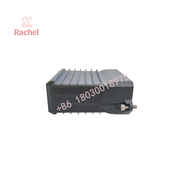
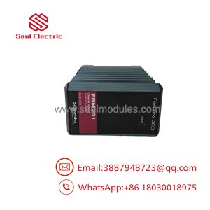
FBMSVH
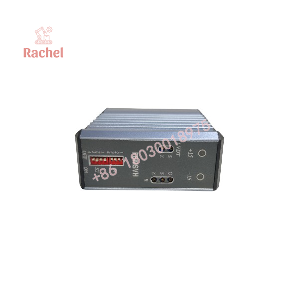
FBMSVH
Engineering Selection Highlights
- Select FBMSVH when closed-loop position control of a servo valve with LVDT feedback is required.
- Confirm that the command signal type (4–20 mA or 0–10 V) matches the upstream controller output.
- Verify LVDT signal characteristics and wiring compatibility with the on-board modulator/demodulator.
- Ensure an external ±15 VDC supply of adequate capacity is available.
- Adjust proportional gain and integral time to achieve the required response and stability for the specific valve and process.
- Use the external shutdown contact for safety interlocks or emergency trip functions.
- Confirm that the 0–20 mA position feedback signal is correctly scaled and wired to the receiving system.
Dimensions, Mounting & Connection Notes
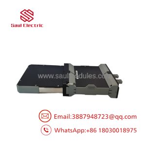
The FBMSVH is typically supplied as a plug-in or panel-mount control card. Exact dimensions vary by revision; consult the specific hardware drawing for the installed version. Field connections include command input, LVDT feedback, servo drive output, position feedback output, external power (±15 VDC), and the shutdown contact. Proper shielding and grounding practices are essential because of the low-level LVDT signals and precision analog circuitry.
System Compatibility & Integration Requirements
| Item / Dependency | Verified Compatibility or Requirement | Practical Note |
|---|---|---|
| System Family | Foxboro I/A Series (and compatible DEH / turbine control systems) | Specialized servo interface card |
| Command Source | 4–20 mA or 0–10 VDC from control processor or DEH | Selectable input type |
| Position Feedback | LVDT (0–10 V) | On-board modulator/demodulator |
| Servo Valve | Compatible with ±27 mA bidirectional drive | Confirm coil resistance and polarity |
| Power Supply | External ±15 VDC | Approx. 250 mA per rail |
| Position Feedback Output | 0–20 mA | For monitoring by the control system |
| Shutdown Input | Dry contact | Forces safe output state |
FAQ
What is the Foxboro FBMSVH?
It is a closed-loop servo control card that uses LVDT feedback to position pneumatic or hydraulic servo valves under P or P+I control.
What command signals does it accept?
4–20 mA or 0–10 VDC.
What is the servo drive output?
Bidirectional current of approximately ±27 mA (up to ±30 mA) to drive the servo valve.
Does it provide position feedback?
Yes. A 0–20 mA output represents the measured valve position.
What power supply is required?
External ±15 VDC, typically drawing about 250 mA from each rail.
Can the output be forced to a safe state?
Yes. An external contact closure can inhibit or force the drive current to a predefined safe value.
Verification & Troubleshooting Notes
- Confirm the module identity by the FBMSVH designation on the label.
- Verify that the external ±15 VDC supplies are present, correctly polarized, and within tolerance.
- Check command input type selection and scaling.
- Confirm LVDT excitation, feedback signal amplitude, and wiring integrity.
- Observe the servo drive current and valve response while adjusting gain and integral settings.
- Test the external shutdown contact to ensure it forces the output to the safe state.
- Verify that the 0–20 mA position feedback signal is correctly received by the monitoring system.
- Replacement or adjustment should be performed only after verifying power, signal integrity, and control configuration.

 Start Chat


