





Description
Key Technical Specifications
| Parameter | Specification |
|---|---|
| Manufacturer | Foxboro |
| Model | FCM2F2 |
| Order code | RH914YZ |
| Product type | Fiber-optic Fieldbus Communications Module |
| System family | Foxboro 200 Series DCS |
| Primary function | Fieldbus communication extension between baseplates |
| Maximum nominal fiber distance | 2 km (1.24 miles) |
| Fiber type | Multimode, graded-index glass fiber |
| Fiber core / cladding | 62.5 / 125 μm |
| Numerical aperture | 0.275 |
| Maximum signal loss | 1 dB/km at 1300 nm; 3.6 dB/km at 850 nm |
| Optical connector | ST-type |
| Redundant input voltage | 24 V DC, +5% / −10% |
| Maximum power consumption | 5 W at 24 V DC |
| Maximum heat dissipation | 5 W at 24 V DC |
| Operating temperature | −20°C to +70°C |
| Operating relative humidity | 5–95%, noncondensing |
| Operating altitude | −300 to +3,000 m |
| Vibration rating | 0.75 g, 5–200 Hz |
| Mounting platform | Standard 200 Series FBM baseplate |
| Module dimensions (H × W × D) | 102 × 45 × 104 mm |
| Height including mounting lugs | 114 mm |
| Approximate weight | 284 g |
| Status indicators | Red, green, and amber LEDs |
Engineering Selection Highlights
- 2 km communication reach: Extends the 200 Series module fieldbus across a nominal fiber distance of up to 2 km between baseplates.
- Specified multimode fiber: Requires 62.5/125 μm graded-index glass fiber with a numerical aperture of 0.275 and ST-type connectors.
- Optical electrical isolation: Fiber communication avoids electrical ground-loop paths between interconnected baseplates and is unaffected by electromagnetic interference on the optical link.
- Redundant configuration support: Redundant installations use paired FCMs on each baseplate; a non-redundant configuration requires one FCM per baseplate.
- 24 V DC power requirement: The documented redundant input range is 24 V DC +5%/−10%, with maximum consumption of 5 W.
- Baseplate-specific installation: The module mounts on a standard 200 Series FBM baseplate rather than serving as a standalone general-purpose fiber converter.
- Front-panel diagnostics: Six LEDs indicate module operational status and communication activity, helping maintenance personnel assess the module and fiber link.
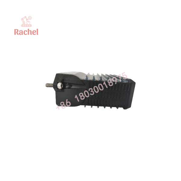
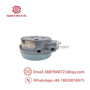
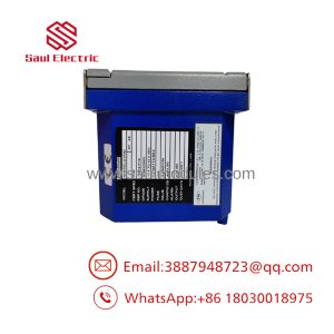
FCM2F2 RH914YZ
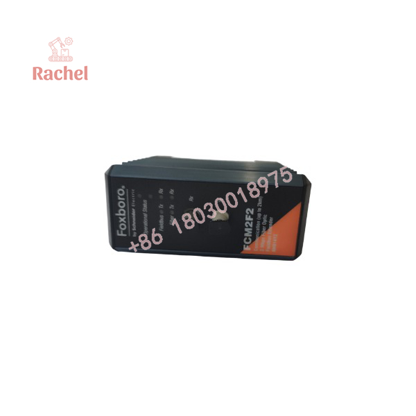
FCM2F2 RH914YZ
System Compatibility & Integration Requirements
| Item | Requirement | Engineering Consideration |
|---|---|---|
| DCS platform | Foxboro 200 Series DCS | Confirm that the installed controller and baseplate architecture supports the FCM configuration. |
| Baseplate | Standard 200 Series FBM baseplate | Verify baseplate type and available mounting positions. |
| Fiber type | 62.5/125 μm multimode graded-index glass fiber | Use the specified fiber characteristics for the FCM2F2 link. |
| Optical connectors | ST-type connectors | Check connector type and cable termination at both ends. |
| Link distance | Up to 2 km nominally between baseplates | Include the complete optical path and account for signal loss. |
| Redundant configuration | Two FCMs per baseplate in the documented redundant arrangement | Redundant FCMs must occupy the first or last adjacent slots on the baseplate. |
| Non-redundant configuration | One FCM per baseplate | Confirm the intended communication architecture before installation. |
| Power supply | 24 V DC, +5%/−10% for the documented redundant supply specification | Confirm the actual baseplate power arrangement and supply capacity. |
| Mounting infrastructure | DIN rail or horizontal 19-inch rack mounting through the applicable baseplate arrangement | Select the appropriate baseplate and mounting hardware. |
| Fiber-loss budget | Maximum allowable loss of 1 dB/km at 1300 nm and 3.6 dB/km at 850 nm | Check the complete link loss against the applicable cable and system requirements. |
The FCM2F2, FCM2F4, and FCM2F10 are different distance variants. The FCM2F2 must be paired with the same type at the opposite end of the fiber link. Do not assume that modules with similar housings or different distance ratings are interchangeable.
Dimensions, Mounting & Connection Notes
The FCM2F2 mounts on a standard Foxboro 200 Series FBM baseplate. The baseplate provides the module’s fieldbus, power, and I/O cable connections.
- Module dimensions: 102 mm high × 45 mm wide × 104 mm deep.
- Height with mounting lugs: 114 mm.
- Weight: Approximately 284 g.
- Mounting options: DIN rail, horizontally or vertically, through the baseplate arrangement; horizontal 19-inch rack installation with the appropriate mounting kit.
- Optical connection: ST-type connectors on the specified multimode fiber cable.
- Front-panel indicators: Red and green LEDs for operational status, and amber LEDs for data traffic and direction.
- Module replacement: The FCM can be removed from or replaced on the baseplate without removing power, subject to the applicable system maintenance procedures.
The module’s environmental limits depend partly on the enclosure in which it is installed. Use the applicable baseplate and enclosure documentation when planning installation in a harsh environment or a classified location.
Detailed Product Overview
Fiber-optic fieldbus extension
The FOXBORO FCM2F2 RH914YZ is designed to extend the Foxboro 200 Series module fieldbus over fiber-optic cable. In a distributed control system, fieldbus communication links the control architecture to the fieldbus modules installed on I/O baseplates. When those baseplates are located remotely, the FCM2F2 provides an optical communication path between them.
The FCM2F2 supports a nominal maximum distance of 2 km between baseplates. The distance rating is a system-selection parameter rather than a guarantee for every cable installation. Cable attenuation, connector losses, and the actual route must remain within the applicable optical requirements.
Fiber selection and electrical isolation
The specified cable is multimode, graded-index glass fiber with a 62.5 μm core and 125 μm cladding. It must use ST-type connectors and meet the documented attenuation limits.
Fiber-optic communication is particularly useful where conventional electrical connections may be affected by electromagnetic interference, lightning-related disturbances, or differences in ground potential. The optical path avoids a conductive signal connection between the linked baseplates, helping prevent ground-loop current through the communication link.
This isolation does not eliminate the need for proper cabinet grounding, power protection, or compliance with the overall control-system installation requirements.
Redundancy and baseplate arrangement
The FCM2F2 supports both redundant and non-redundant configurations. A non-redundant arrangement requires one FCM on each participating baseplate. A redundant connection uses a pair of FCMs at each baseplate, requiring four modules when two baseplates are connected in the documented redundant arrangement.
In redundant installations, the FCMs must occupy the designated adjacent end positions on the baseplate. The modules at the two ends of a fiber link must be the same distance variant. These placement and pairing rules should be checked before adding or replacing a module.
Power and diagnostic information
The documented redundant input-voltage specification is 24 V DC, +5%/−10%. Maximum power consumption and heat dissipation are each specified as 5 W at 24 V DC.
Six front-panel LEDs provide operational and communication indications. Red and green indicators report FCM operating status, while amber indicators show fieldbus and fiber-link data activity and direction. These indicators help narrow down communication faults, although the LED state must be interpreted using the system’s applicable diagnostic documentation.
Mechanical and environmental fit
The module measures 102 × 45 × 104 mm, with a height of 114 mm including mounting lugs, and weighs approximately 284 g. It mounts on a standard 200 Series FBM baseplate, which can be installed on DIN rail or horizontally in a 19-inch rack with the appropriate mounting kit.
The specified operating temperature range is −20°C to +70°C, with relative humidity of 5–95% noncondensing. For replacement planning, verify the baseplate type, power arrangement, fiber specifications, and module variant before installation.
Applications & System Role
The FCM2F2 functions as an optical extension of the Foxboro 200 Series module fieldbus. Its purpose is to let remote FBMs operate closer to field devices while retaining a communication path to the main control system.
Typical engineering use cases include:
- Remote I/O baseplates: Extending fieldbus communication to an I/O location separated from the primary controller or cabinet.
- Electrically noisy installations: Using fiber-optic communication in areas with rotating machinery, arc welding equipment, or nearby high-voltage power cables.
- Ground-potential separation: Connecting baseplates where electrical isolation between communication segments is important.
- Distributed process-control cabinets: Reducing the need for long electrical fieldbus cable runs between remote I/O locations.
- Redundant fieldbus architecture: Providing paired modules and fiber connections in installations designed for redundant communication paths.
These scenarios describe the module’s documented functional role; suitability for a specific plant depends on the installed DCS architecture, baseplate configuration, cable route, and system design.
FAQ
What is the FOXBORO FCM2F2 RH914YZ?
It is a Foxboro 200 Series Fieldbus Communications Module that extends module fieldbus communication over multimode fiber-optic cable.
What is the maximum communication distance?
The FCM2F2 supports a nominal maximum fiber-optic distance of 2 km (1.24 miles) between baseplates.
Which fiber-optic cable does the FCM2F2 require?
It requires multimode, graded-index glass fiber with a 62.5 μm core, 125 μm cladding, a numerical aperture of 0.275, and ST-type connectors. The specified maximum signal loss is 1 dB/km at 1300 nm and 3.6 dB/km at 850 nm.
Can the FCM2F2 operate in a redundant configuration?
Yes. The documented redundant arrangement uses two FCMs on each baseplate, with the modules installed in designated adjacent end positions. The modules at both ends of the fiber link must be the same type.
What is the power requirement for the FCM2F2?
The documented redundant input-voltage range is 24 V DC +5%/−10%. Maximum power consumption is 5 W at 24 V DC.
What are the module’s dimensions and mounting requirements?
The module measures 102 × 45 × 104 mm, or 114 mm high including mounting lugs, and weighs approximately 284 g. It mounts on a standard Foxboro 200 Series FBM baseplate.
What operating conditions does the FCM2F2 support?
The documented operating temperature is −20°C to +70°C, relative humidity is 5–95% noncondensing, and operating altitude is −300 to +3,000 m.
Can the FCM2F2 be replaced without powering down the baseplate?
The module is designed to be removed or replaced from the baseplate without removing power. Follow the applicable Foxboro system maintenance procedures and confirm the installation’s operating requirements before carrying out replacement work.

 Start Chat


