





Description
Product Introduction & Engineering Value
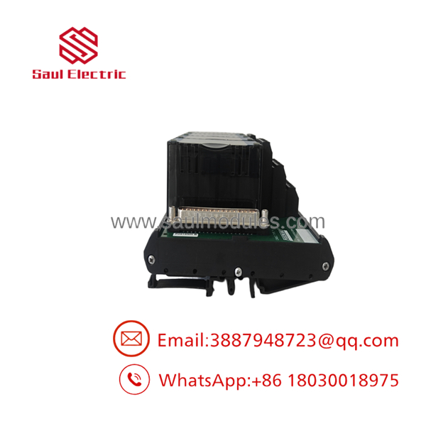
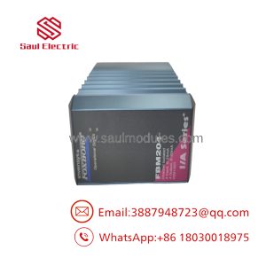
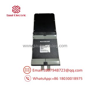
When an FBM242 installation has a field-side termination problem, P0916NG is the component to investigate—not the FBM242 electronics by default. Foxboro documentation identifies P0916NG within the FBM242 termination-assembly family, while the FBM242 itself performs the discrete I/O and ladder-logic functions.
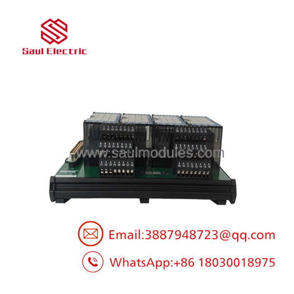
The P0916NG configuration uses two-tier compression terminals and is intended for externally sourced discrete outputs. This makes correct identification especially important in cabinets containing multiple termination assemblies with similar physical dimensions.
Technical Specifications
| Parameter | Specification |
|---|---|
| Manufacturer | Foxboro |
| Part Number | P0916NG |
| Associated Module | FBM242 |
| System | I/A Series |
| Hardware Type | Termination Assembly |
| Termination Configuration | 2-tier compression |
| Number of Output Positions | 16 |
| Output Type | Externally sourced discrete output |
| Supported DC Voltage | 15–60 VDC |
| Maximum Output Current | 2.25 A/channel |
| Maximum Inrush Current | 8 A for 20 ms at 30°C |
| On-State Voltage Drop | 0.2 V maximum at 2.25 A |
| Off-State Leakage | 0.1 mA maximum |
| Isolation | Individual channel galvanic isolation |
| Mounting | DIN-rail termination assembly |
Foxboro’s PSS 21H-2Z42 documentation states that the FBM242 contains 16 discrete outputs, rated up to 2 A at 60 VDC in the module description, while the detailed termination specifications list up to 2.25 A per channel for the relevant output interface. Each output is isolated from the other channels and ground.
Output architecture
P0916NG belongs to the termination family supporting externally sourced discrete outputs. The broader TA family includes arrangements for solid-state outputs, relays, fusing, and power distribution.
That matters when replacing an installed assembly. Match the actual termination configuration rather than assuming all TAs are equivalent.
Field Application & the “Trench” Experience
Consider an older process-control cabinet where an drives multiple solenoid valves and contactors. One field output starts showing intermittent operation. The PLC/DCS diagnostic indicates an output command, but the field actuator does not consistently energize.
A technician checks the and sees the expected output state. The next inspection point is the field termination. A loose or damaged compression connection on P0916NG can produce exactly the kind of field symptom that initially looks like an I/O electronics failure.
The correct maintenance sequence is simple: verify the command, verify the FBM, then verify the termination and field circuit.
Specific application scenarios
- Solenoid-valve actuation using externally supplied DC power.
- Motor starter/interposing relay control from discrete DCS outputs.
- Process skid shutdown or permissive circuits requiring multiple isolated discrete outputs.
- Legacy I/A Series control cabinets where termination hardware remains in service.
P0916NG
P0916NG
Transparency SOP: QA & Testing
For , use a hardware-focused inspection procedure:
- Part-number confirmation — verify
on the actual assembly. - Configuration check — confirm the hardware is the two-tier compression version.
- Terminal inspection — examine all 16 positions for damaged clamps, corrosion, contamination, or deformation.
- Mounting inspection — check the DIN-rail interface and mechanical housing.
- Cable/interface check — verify compatibility with the termination cable.
- Electrical verification — where test equipment permits, perform continuity and interface checks without applying excessive test voltage.
- Traceability — document packaging, date/revision information, photographs, and serial markings when present.
For refurbished stock, functional verification should also confirm that the termination interface does not introduce excessive resistance or intermittent connections.
The Veteran’s Tech Trap Guide
⚠️ Trap #1 — Calling the
is the termination assembly. is the associated discrete-output interface module. Several commercial listings incorrectly collapse the two into one product description.
PRO TIP: Put both identifiers on the purchase request: “ termination assembly for .” It removes a lot of ambiguity.
⚠️ Trap #2 — Ignoring the output voltage
The / architecture can be used with externally sourced discrete outputs across different voltage arrangements. The documented supports 15–60 VDC, while other termination assemblies in the same family accommodate AC or higher-voltage applications.
Do not substitute a relay or high-voltage termination assembly simply because the connector looks similar.
⚠️ Trap #3 — Assuming 2.25 A means every field load is acceptable
The documented 2.25 A/channel figure is a hardware limit, not a recommendation for every load. Solenoids, contactors, and other inductive loads have inrush and switching characteristics that must be considered.
The Foxboro documentation specifically notes that inductive loads may require a protective diode or MOV.
Dynamic FAQ
What is Foxboro ?
is a two-tier compression termination assembly associated with the Foxboro externally sourced discrete-output module.
How many outputs does the / configuration support?
The provides 16 isolated discrete outputs.
What voltage does support?
The documented externally sourced output architecture supports 15–60 VDC. The broader termination family also includes separate arrangements for 120 VAC/125 VDC and 240 VAC applications.
Is a compression termination assembly?
Yes. Commercial records specifically identify it as “ 2TIER COMPRESSION,” consistent with the Foxboro documentation describing the termination-assembly family.
Can I replace with another termination assembly?
Not automatically. The family contains multiple termination configurations for different field-output requirements. Verify termination style, output voltage, relay/solid-state arrangement, fusing, and power-distribution requirements before substituting.
What should I verify when buying New Surplus ?
Confirm the complete part number, two-tier compression configuration, physical condition, compatibility, terminal condition, traceability, and supplier warranty. For a critical DCS spare, request photographs of the actual unit rather than relying solely on a catalog image.

 Start Chat


