





Description
Product Introduction & Engineering Value
RH926GK is a legacy Foxboro relay/interface part number intended for use within compatible control-system hardware. Its exact electrical function should be established from the parent assembly and technical documentation rather than treating it as a generic replacement relay.
During procurement, verify the complete part number, associated Foxboro assembly, coil requirements, contact arrangement, and load characteristics. That information determines whether a proposed replacement is actually suitable.
Technical Specifications
| Parameter | Specification |
|---|---|
| Part Number | RH926GK |
| Manufacturer | Foxboro / Invensys |
| Product Family | Foxboro I/A Series |
| Hardware Category | Relay/interface component |
| Primary Function | Signal switching/interface |
| System Application | Industrial process control |
| Mounting | Assembly-dependent |
| Coil/Input Rating | Verify from exact component documentation |
| Contact Rating | Verify from exact documentation |
| Contact Configuration | Verify before substitution |
| Connection Method | Assembly-dependent |
| Replacement Requirement | Exact electrical and mechanical match |
Engineering note
I would not assign a specific coil voltage, contact configuration, contact current, or switching capacity to RH926GK without documentation specifically tied to this part number.
That is intentional. For legacy relay hardware, guessing those values can lead to a bad replacement decision. Verify the actual relay marking, parent assembly documentation, or Foxboro technical drawing before energizing or substituting the component.
Field Application & the “Trench” Experience
A relay interface often gets blamed after a field output stops working. In a legacy Foxboro cabinet, the operator sees a valid command, but the downstream actuator does not respond. The technician finds that the control-system output reaches the relay interface, yet the expected field-side contact is absent.
The correct troubleshooting sequence is not simply “replace the relay.”
Check the driving output. Check the coil circuit. Check relay contact transfer. Then inspect the field load and wiring. If RH926GK is confirmed defective, replace it with a component matching the documented electrical configuration.
Niche application scenarios
- Motor starter interface: intermediate relay switching between control outputs and starter circuits.
- Valve actuator command: relay isolation between control logic and field actuator circuitry.
- Alarm interface: dry-contact switching to external annunciation or auxiliary control equipment.
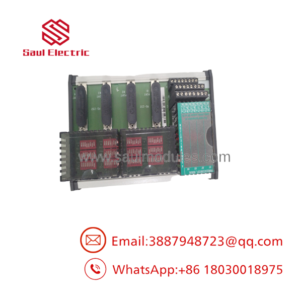
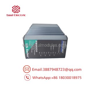
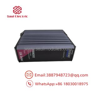
RH926GK
RH926GK
Transparency SOP: QA & Testing
For New Surplus or Refurbished RH926GK stock:
- Verify identity — Confirm RH926GK on the actual component or assembly label.
- Inspect physically — Check terminals, housing, connector interfaces, discoloration, corrosion, and heat damage.
- Confirm coil rating — Establish the rated coil voltage before applying power.
- Check coil resistance — Compare the measured value with the applicable specification where documented.
- Test contacts — Verify the documented contact states and transfer behavior.
- Perform functional testing — Energize at the specified coil voltage and confirm switching operation.
- Document results — Record the test voltage, measured values, condition, and warranty.
QA rule: “Tested” should always be accompanied by a description of the test performed.
The Veteran’s Tech Trap Guide
⚠️ Trap #1 — Applying an assumed coil voltage
Never assume is a 24 VDC coil.
PRO TIP: Confirm the coil rating from the physical marking or applicable Foxboro documentation before applying power.
⚠️ Trap #2 — Treating coil continuity as proof of a good relay
A relay can have a normal coil resistance while its contacts are burned, welded, contaminated, or mechanically unreliable. Test both sides of the device.
⚠️ Trap #3 — Ignoring the switched load
When a relay drives an inductive load, inspect suppression components and load current. A recurring relay failure may originate downstream rather than in the relay itself.
Dynamic FAQ
What is Foxboro ?
is a Foxboro legacy relay/interface part number used within compatible industrial control hardware.
What is the coil voltage?
The coil voltage should be confirmed from the actual component marking or applicable Foxboro documentation. It should not be inferred from the model number.
What contact configuration does use?
The exact contact configuration should be verified from the original component or relevant assembly documentation before replacement.
Can a generic relay replace ?
Only after an engineering equivalency check. Verify coil voltage, contact arrangement, current/voltage ratings, insulation requirements, terminal configuration, mounting, and load type.
What should I request when purchasing New Surplus ?
Request actual-unit photographs, complete identification markings, condition details, coil/contact test results, and written warranty terms. For a relay, ask specifically whether both coil operation and contact switching were tested.
Is supplied with a warranty?
Warranty coverage depends on the supplier and inventory condition. For a critical Foxboro spare, specify the warranty duration and return procedure in the purchase documentation.

 Start Chat


